Ide, connectors j15 and j16 – Xilinx ML310 User Manual
Page 44
44
ML310 User Guide
1-800-255-7778
UG068 (v1.01) August 25, 2004
Chapter 2: ML310 Embedded Development Platform
R
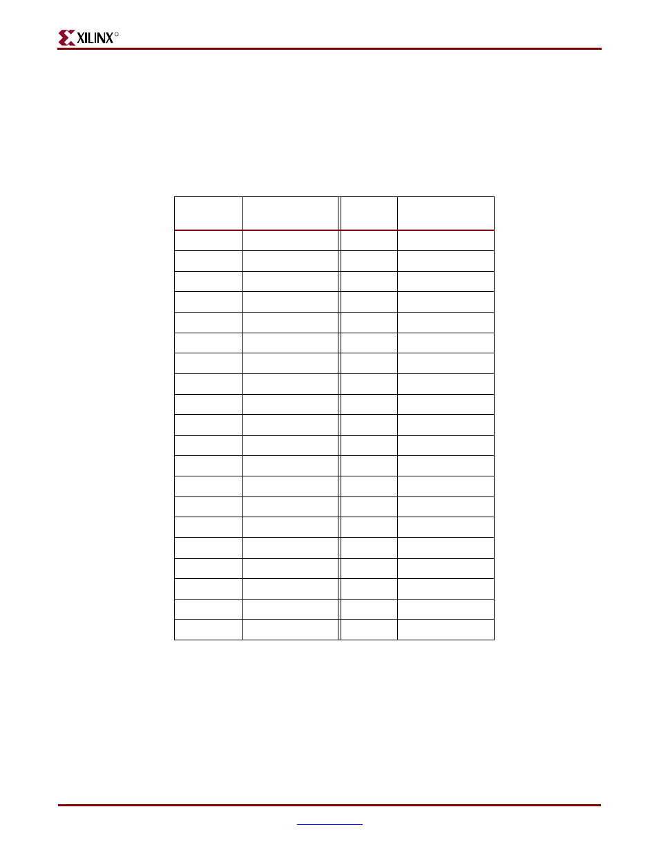
IDE, connectors J15 and J16
Supports a 2-channel UltraDMA-133 IDE Master controller independently connected to a
Primary 40 Pin IDC connector (J16) and a Secondary 40 Pin IDC connector (J15). Please
review the ALi M1535D+ Data sheets for more detailed information.
shows the ALi Primary and Secondary IDE connections to the two 40 pin IDE
Connectors, J15 and J16.
Table 2-16:
ALi South Bridge IDE connectors, J15 and J16
J15/J16
Pin No.
Schem Signal
J15/J16
Pin No.
Schem Signal
1
IDE_RESET_N
2
GND
3
IDE_D7
4
IDE_D8
5
IDE_D6
6
IDE_D9
7
IDE_D5
8
IDE_D10
9
IDE_D4
10
IDE_D11
11
IDE_D3
12
IDE_D12
13
IDE_D2
14
IDE_D13
15
IDE_D1
16
IDE_D14
17
IDE_D0
18
IDE_D15
19
GND
20
(KEY)
21
IDE_DMARQ
22
GND
23
IDE_DIOW_N
24
GND
25
IDE_DIOR
26
GND
27
IDE_IORDY
28
CSEL
29
IDE_DMACK_N
30
GND
31
IDE_INTRQ
32
N.C.
33
IDE_A1
34
IDE_PDIAG_N
35
IDE_A0
36
IDE_A2
37
IDE_CS1_N
38
IDE_CS3_N
39
IDE_DASP_N
40
GND