Usb, connector assembly j3 – Xilinx ML310 User Manual
Page 43
ML310 User Guide
43
UG068 (v1.01) August 25, 2004
1-800-255-7778
Board Hardware
R
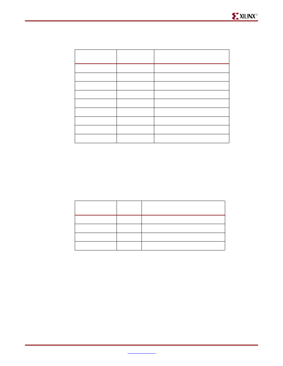
shows the RS-232 signals connected to the two DB9 connectors, P1 A/B.
USB, connector assembly J3
The M1535D+ USB is an implementation of the Universal Serial Bus (USB) 1.0a
specification that contains two (2) PCI Host Controllers and an integrated Root Hub. The
two USB connectors, A/B, are part of the J3 connector assembly and are USB Type-A plugs.
Please review the ALi M1535D+ Data sheets for more detailed information.
shows the ALi USB connections to the two USB Type-A plugs, J3 A/B.
Table 2-14:
ALi South Bridge DB9 Serial Port pinouts, P1 (DB9-A/B)
Signal Name
P1 (DB9-A/B)
Pin No.
Description
DCD
1
Data Carrier Detect
RD
2
Receive Data (a.k.a RxD, Rx)
TD
3
Transmit Data (a.k.a TxD, Tx)
DTR
4
Data Terminal Ready
SGND
5
Ground
DSR
6
Data Set Ready
RTS
7
Request To Send
CTS
8
Clear To Send
RI
9
Ring Indicator
Table 2-15:
ALi South Bridge USB Type-A connector, J3 A/B
Signal Name
J3 (A/B)
Pin No.
Description
USB_VCC
1
USB Power, 5.0V, MOSFET Isolated
USB_DN
2
USB Data -
USB_DP
3
USB Data +
GND
4
Ground