Serial port interface, connector assembly p1 – Xilinx ML310 User Manual
Page 42
42
ML310 User Guide
1-800-255-7778
UG068 (v1.01) August 25, 2004
Chapter 2: ML310 Embedded Development Platform
R
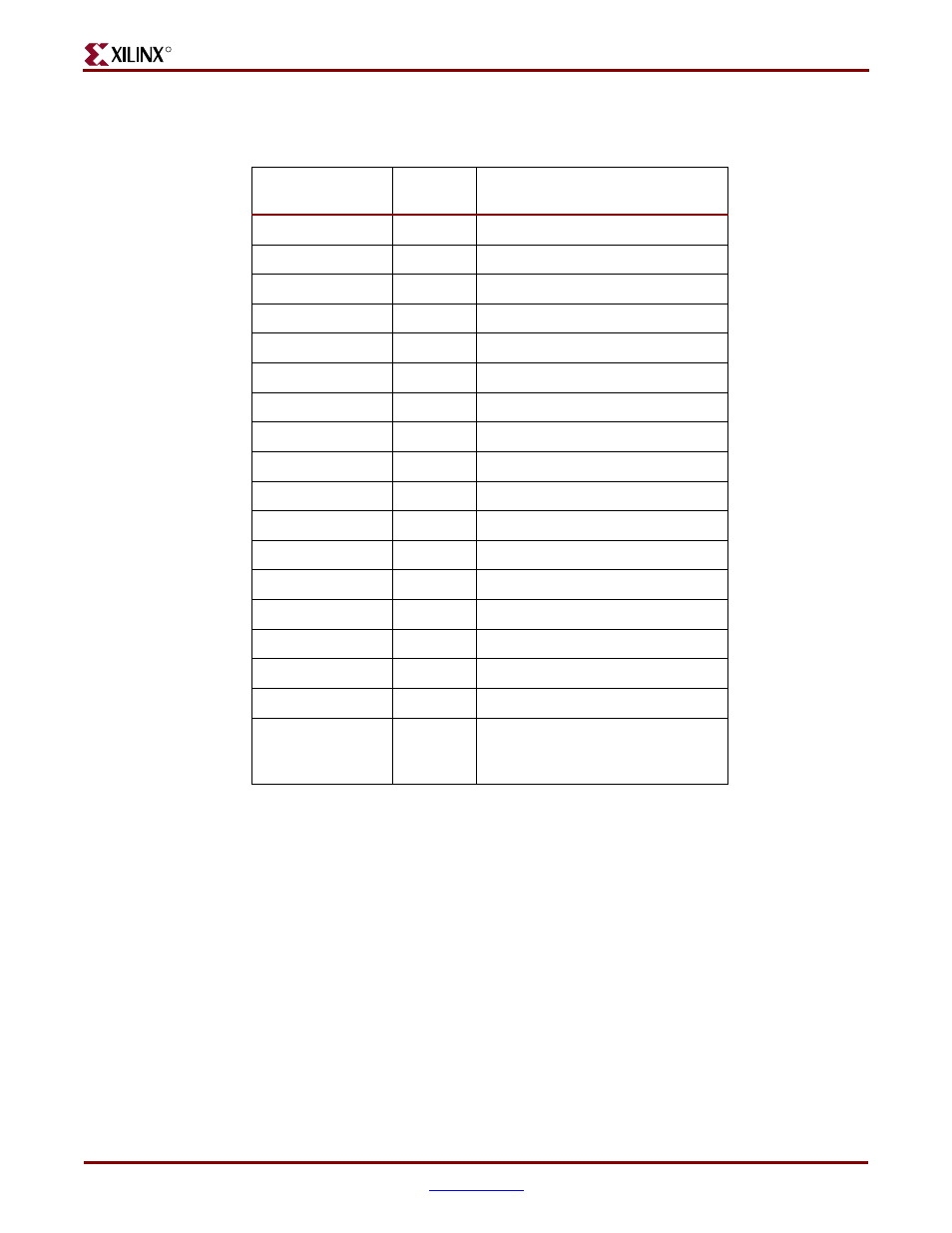
shows the ALi Parallel Port connections to P1, DB25.
Serial Port Interface, connector assembly P1
In addition to the serial port accessible via the XC2VP30 FPGA, the ALi M1535D+ provides
access over the PCI Bus to two serial ports. The ALi M1535D+ employs 16450/16550
Compatible UARTs with Send/Receive16-byte FIFOs. The two Serial ports are connected
to the ALi M1535D+ device via two male DB9 connectors (P1). The DB9 connectors are
configured as DTE interfaces and meet the EIA/TIA-574 standard.
The DB9 male connectors are labeled Serial Port A and B in the ML310 schematics. The DB9
connectors are part of the P1 connector assembly. Please note that Serial Port B is located
adjacent to the PS/2 connector where COM1 in a legacy PC is traditionally located. The
two DB9 serial port connectors are labeled on the ML310 board silk-screen near the P1
connector assembly. Please review the ALi M1535D+ Data sheets for more detailed
information.
Table 2-13:
ALi South Bridge Parallel Port pinout P1 (DB25)
Signal Name
P1 (DB25)
Pin No.
Description
STROBE_N
1
Strobe
D0
2
Data Bit 0
D1
3
Data Bit 1
D2
4
Data Bit 2
D3
5
Data Bit 3
D4
6
Data Bit 4
D5
7
Data Bit 5
D6
8
Data Bit 6
D7
9
Data Bit 7
ACK_N
10
Acknowledge
BUSY
11
Busy
PEND
12
Paper End
SELECT
13
Select
AUTOFD_N
14
Autofeed
ERROR_N
15
Error
INIT_N
16
Initialize
SLCTIN_N
17
Select In
GND
18, 19, 20,
21, 22, 23,
24, 25
Ground