Hardware installation – Western Telematic SRM-100 User Manual
Page 12
4.
Hardware Installation
4.1. Connecting Power to the SRM-100
The SRM-100 is available in both AC and DC powered versions. When connecting power to
the SRM, proceed as follows:
CAUTION: This device should only be operated with the type of power source
indicated on the instrument nameplate. If you are not sure of the type of power
service available, please contact your local power company.
4.1.1.
AC Powered Units
Set the Voltage Selector Switch (located on the SRM back panel) to the appropriate voltage.
Plug the supplied power cable into the receptacle on the SRM-100 back panel, and then connect
the power cable to a grounded (earthed), 115 VAC outlet.
4.1.2.
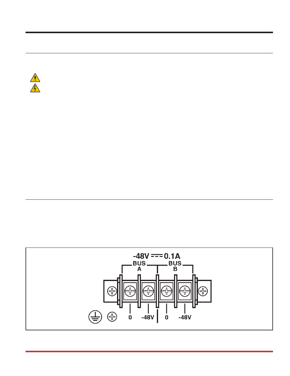
DC Powered Units
When connecting the SRM to your DC power source, first remove the protective plastic cover
from the DC terminal block. Switch off your DC power source, and then attach the wires from
the 48V DC power source to the screw terminals, and connect your ground line to the labeled
ground screw. Then replace the protective cover, and switch the DC power source back on.
Note that the DC terminal block features a dual bus configuration to allow connection to a
back-up power supply.
4.2. SetUp Switches
The SetUp Switches, located on the back panel, select the default settings for Modem Port baud
rate, flow control, parity, rings to answer, and enable/disable ARQ/Compression, the modem
speaker, and the SRM-100 Security Mode.
Note: Operating values for all of these parameters can also be selected via the
SRM’s configuration menus. However, if the unit is reset to default parameters,
these settings will return to the default values selected by the SetUp switches.
4-1
Figure 4.1: Terminal Block Assembly and Grounding Screw (DC Units Only)