Alnctl), Descriptions, Section 2.4.12 – Texas Instruments TMS320C642x DSP User Manual
Page 29
www.ti.com
2.4.12
PLL Controller Clock Align Control Register (ALNCTL)
PLL Controller
The PLL controller clock align control register (ALNCTL) is shown in
and described in
.
ALNCTL indicates which SYSCLKs need to be aligned for proper device operation. You should not modify
ALNCTL from its default settings.
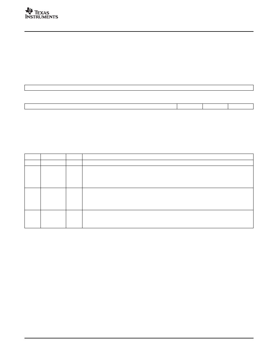
Figure 15. PLL Controller Clock Align Control Register (ALNCTL)
31
16
Reserved
R-0
15
3
2
1
0
Reserved
ALN3
ALN2
ALN1
R/W-0h or 3h
(1)
R/W-0 or 1
(2)
R/W-0 or 1
(3)
R/W-0 or 1
(4)
LEGEND: R/W = Read/Write; R = Read only; -n = value after reset
(1)
For PLLC1, this reserved field defaults to 3h; for PLLC2, this reserved field defaults to 0h. User must not oppose the default value.
(2)
For PLLC1, ALN3 defaults to 1; for PLLC2, ALN3 is reserved and defaults to 0.
(3)
For PLLC1, ALN2 defaults to 1; for PLLC2, ALN2 is reserved and defaults to 0.
(4)
For PLLC1, ALN1 defaults to 1; for PLLC2, ALN1 defaults to 0.
Table 21. PLL Controller Clock Align Control Register (ALNCTL) Field Descriptions
Bit
Field
Value
Description
31-3
Reserved
0
Reserved. User must not oppose the default value.
2
ALN3
SYSCLK3 needs to be aligned to others selected in this register. Not applicable on PLLC2 (this bit is
reserved).
0
SYSCLK3 does not need to be aligned.
1
SYSCLK3 does need to be aligned.
1
ALN2
SYSCLK2 needs to be aligned to others selected in this register. Not applicable on PLLC2 (This bit is
reserved).
0
SYSCLK2 does not need to be aligned.
1
SYSCLK2 does need to be aligned.
0
ALN1
SYSCLK1 needs to be aligned to others selected in this register.
0
SYSCLK1 does not need to be aligned.
1
SYSCLK1 does need to be aligned.
SPRUES0B – December 2007
Phase-Locked Loop Controller (PLLC)
29