Appendix 3 interface – Toshiba B-850 User Manual
Page 76
APPENDIX 3 INTERFACE
EO1-33029
APPENDIX 3 INTERFACE
A3-1
APPENDIX 3 INTERFACE
Interface Cables
To prevent radiation and reception of electrical noise, the interface cables must meet the following
requirements:
•
Fully shielded and fitted with metal or metallized connector housings.
•
Keep as short as possible.
•
Should not be bundled tightly with power cords.
•
Should not be tied to power line conduits.
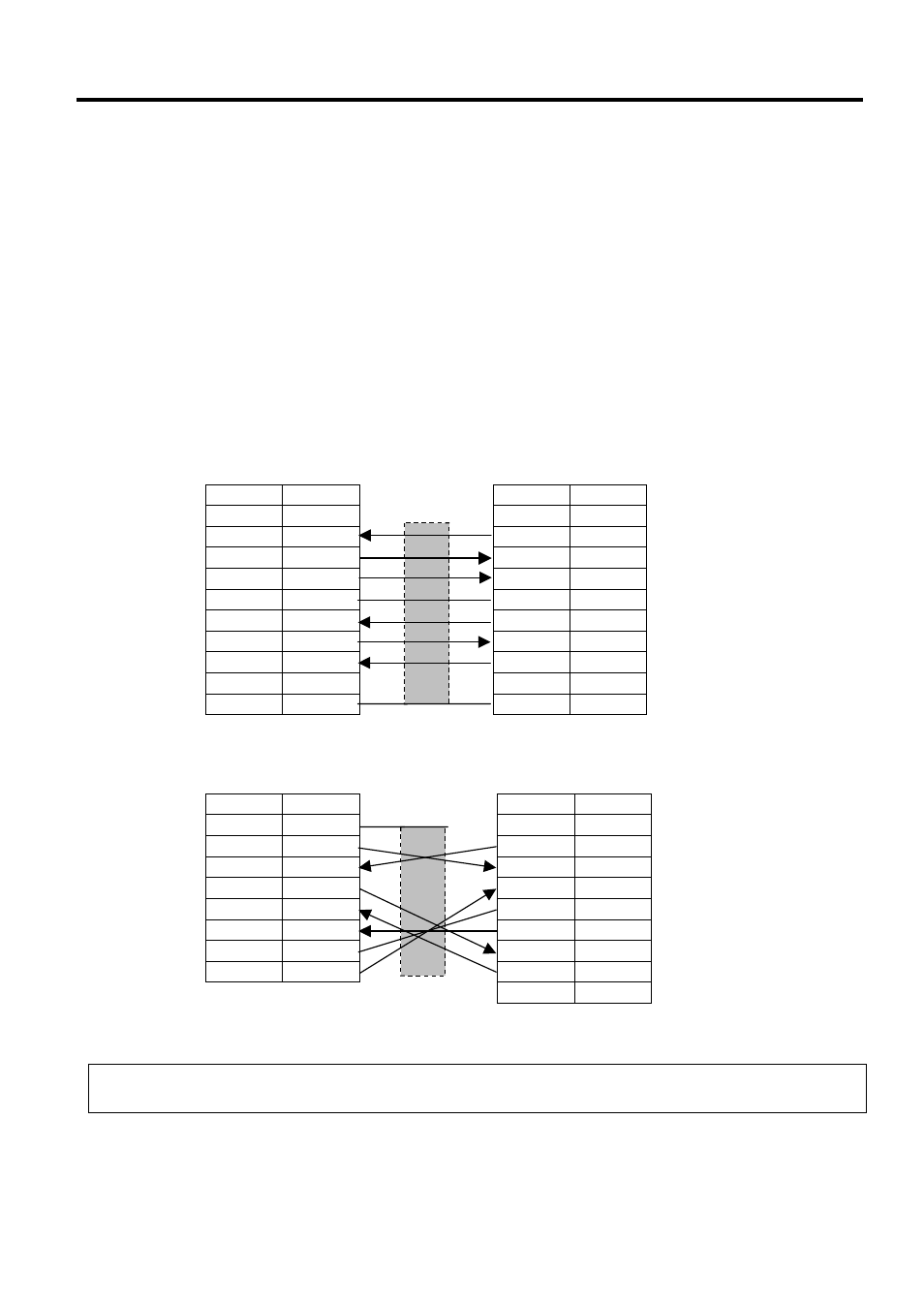
RS-232C Cable description
The serial data cable used to connect the printer to the host computer should be one of the following two
types:
NOTE:
Use an RS-232C cable with inch type securing screws on the connector.
DB-9S
Connector to PC
Pin No.
Signal
1 N.C.
2 RXD
3 TXD
4 DTR
5 GND
6 DSR
7 RTS
8 CTS
9 N.C.
Housing Shield
DB-9P
Connector to Printer
Pin No.
Signal
1 N.C.
2 TXD
3 RXD
4 DSR
5 SG
6 DTR
7 CTS
8 RTS
9 N.C.
Housing Shield
DB-25S
Connector to PC
Pin No.
Signal
1 Shield
2 TXD
3 RXD
4 RTS
5 CTS
6 DSR
7 GND
20 DTR
DB-9P
Connector to Printer
Pin No.
Signal
1 N.C.
2 TXD
3 RXD
4 DSR
5 SG
6 DTR
7 CTS
8 RTS
9 N.C.