TOYOTA 2005 CAMRY User Manual
Page 106
2005 CAMRY (EWD586U)
123
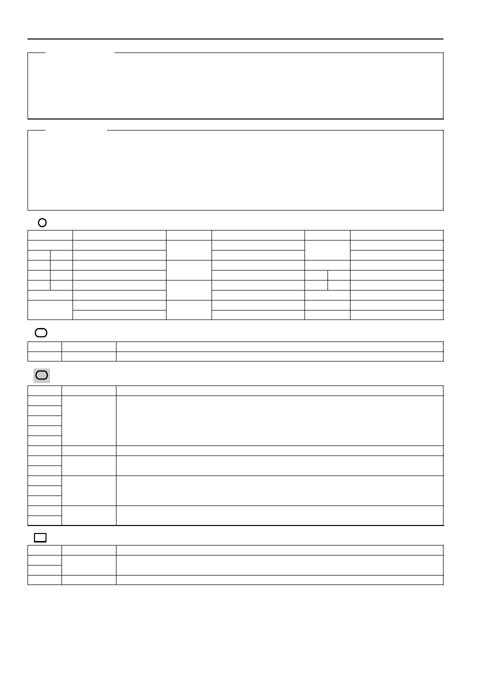
Daytime Running Light Operation
When the engine is started, a signal from the generator is input into TERMINAL (B) 18 of the body ECU. At this time, if the
parking brake pedal is depressed or parking brake lever is pulled (Parking brake SW ON), the body ECU is not activated,
and the daytime running light system does not operate.
When the parking brake pedal or parking lever is released (Parking brake SW OFF), a signal is input into TERMINAL 18 of
the body ECU. This activates the body ECU and the headlight turns on.
Body ECU
9–Ground : Approx. 12 volts with the ignition SW at ON or ST position
12, 24–Ground : Always continuity
1–Ground : Always approx. 12 volts
P3 Parking Brake SW
1–Ground : Continuity with the parking brake pedal depressed (Pedal type)
Continuity with the parking brake lever pulled up (Lever type)
: Parts Location
Code
See Page
Code
See Page
Code
See Page
A38
40
G2
36 (*1)
H4
36 (*1)
B6
A
40
G2
38 (*2)
H4
38 (*2)
B7
B
40
H1
36 (*1)
J4
41
C7
A
40
H1
38 (*2)
J22
A
41
C8
B
40
H2
36 (*1)
J23
B
41
C11
40
H2
38 (*2)
P3
41
D16
36 (*1)
H3
36 (*1)
D16
38 (*2)
H3
38 (*2)
: Relay Blocks
Code
See Page
Relay Blocks (Relay Block Location)
1
22
Engine Room R/B (Engine Compartment Left)
: Junction Block and Wire Harness Connector
Code
See Page
Junction Block and Wire Harness (Connector Location)
1C
1E
1F
25
Engine Room Main Wire and Engine Room J/B (Engine Compartment Left)
1G
g
g
(
g
)
1H
2B
28
Instrument Panel Wire and Driver Side J/B (Lower Finish Panel)
2F
28
Engine Room Main Wire and Driver Side J/B (Lower Finish Panel)
2G
28
Engine Room Main Wire and Driver Side J/B (Lower Finish Panel)
2L
2R
29
Instrument Panel Wire and Driver Side J/B (Lower Finish Panel)
2S
(
)
3A
34
Instrument Panel Wire and Passenger Side J/B (Instrument Panel Brace RH)
3B
34
Instrument Panel Wire and Passenger Side J/B (Instrument Panel Brace RH)
: Connector Joining Wire Harness and Wire Harness
Code
See Page
Joining Wire Harness and Wire Harness (Connector Location)
IF2
50
Engine Room Main Wire and Instrument Panel Wire (Right Side of Steering Column Tube)
IF3
50
Engine Room Main Wire and Instrument Panel Wire (Right Side of Steering Column Tube)
IL2
52
Engine Wire and Instrument Panel Wire (Behind the Glove Box)
* 1 : 1MZ–FE, 3MZ–FE
* 2 : 2AZ–FE
* 3 : w/ Power Seat
* 4 : w/o Power Seat
System Outline
Service Hints