RAD Data comm TDMoIP Gateway IPmux-16 User Manual
Page 29
IPmux-16 Installation and Operation Manual
Chapter 2 Installation
Equipment Needed
2-3
Table 2-1. Null Cable Pinout Connections
DB-9 Female
Pin No.
Signal
Name
1
DCD
Data Carrier Detect
2 RXD
Receive
data
3
TXD
Transmit data
4
DTR
Data Terminal Ready
5 GND
Ground
6
DSR
Data Set Ready
7
RTS
Request To Send
8
CTS
Clear To Send
9
RI
Ring Indicator
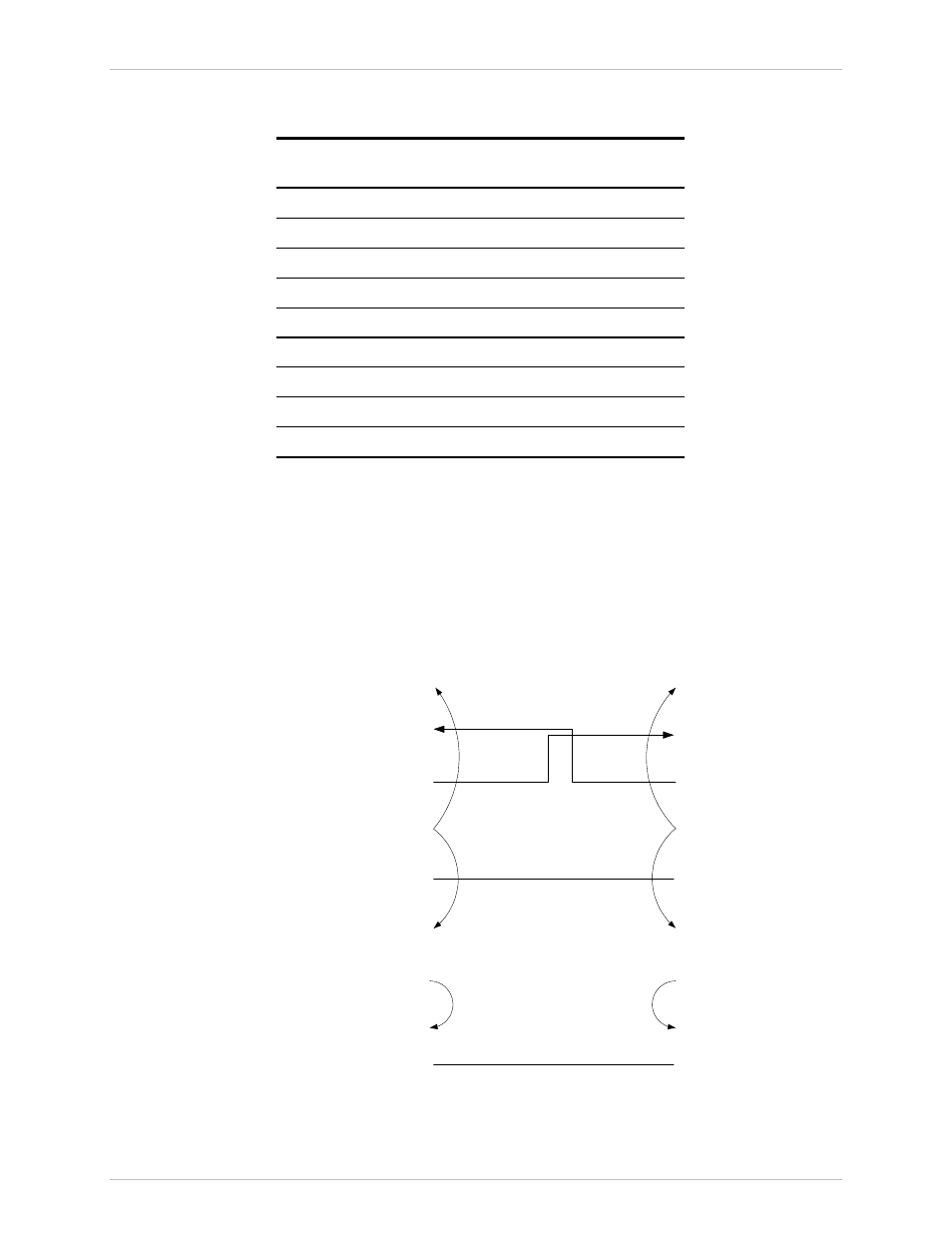
On both DB9 connectors, DCD (pin 1), DTR (pin 4) and DSR (6) are connected
together.
RTS (pin 7) is shorted together with CTS (pin 8). Refer to Figure 2-1.
CBL-DB-9/DB9/NULL
DB-9 (Female)
DB-9 (Female)
1
2
3
4
5
7
8
6
9
9
8
7
6
5
4
3
2
1
Figure 2-1. Null Cable (CBL-DB-9/DB-9/NULL) Pin Shorts