Front panel, Rear panel, Functional description – RAD Data comm TDMoIP Gateway IPmux-16 User Manual
Page 14: 3 functional description
Chapter 1 Introduction
IPmux-16 Installation and Operation Manual
1-6 Functional Description
Front Panel
The control port and indicator LEDs are located on the front panel of IPmux-16.
For further details see Chapter 2.
Rear Panel
Fuses, power supplies, the dry contact connector, and interface connectors are
located on the rear panel of IPmux-16. For further details see Chapter 2.
1.3 Functional Description
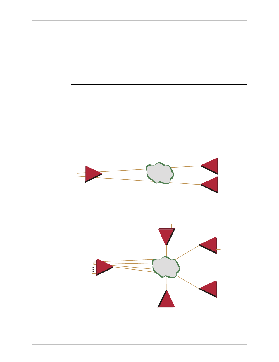
IPmux-16 modules support E1 or T1 TDM interfaces. The E1 and T1 modules have
either four or eight ports. Each bundle (group of timeslots) can be transmitted to a
predefined destination bundle (see the following figure). IPmux-16 supports ICMP
(ping), and generates ARP in case of unknown next hop MAC addresses, answers
ARP requests, and supports 802.3 Ethernet format.
Configuration and management are provided via the IPmux-16 local terminal,
Telnet application or SNMP such as RADview, RAD’s Network Management
System.
IP over
Ethernet
IPmux-16
E1/T1 Port 1
E1/T1 Port 2
IPmux-16
IPmux-16
E1/T1 Port 1
E1/T1 Port 2
Figure 1-4. IPmux-16 Point-to-Point Application
IPmux-1
IPmux-1
IPmux-4
E1/T1 Line 1
E1/T1 Line 2
E1/T1 Line 16
IPmux-16
Sub E1/T1
Sub E1/T1
Sub E1/T1
Sub E1/T1
IP over
Ethernet
IPmux-16
Figure 1-5. Grooming of Timeslots from Remote Sites into a
Single E1/T1 Port at Central Site