Rear panel – Roland V-Synth GT User Manual
Page 24
24
Panel Descriptions
00b-03.eps
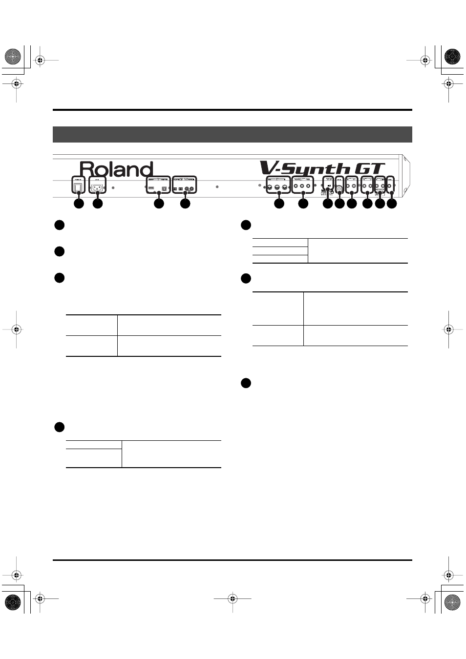
POWER Switch
This switch turns the power on/off.
AC Inlet
Connect the included power cord to this inlet.
USB Connectors
These are USB connectors. They allow the V-Synth GT to be
connected to your computer to transfer files (p. 221) or to
transmit and receive MIDI and audio data.
* In order to use the USB MIDI and audio functionality, you’ll need to
install the USB driver in your computer as described in the separate
“Driver Installation Guide.”
* Never insert or remove a USB memory while this unit’s power is on.
Doing so may corrupt the unit’s data or the data on the USB memory.
* Carefully insert the USB memory all the way in—until it is firmly in
place.
DIGITAL AUDIO Connectors
MIDI Connectors
FOOT PEDAL Jacks
* Use only the specified expression pedal (EV series; sold separately).
By connecting any other expression pedals, you risk causing
malfunction and/or damage to the unit.
PHANTOM Switch
This switch turns the phantom power on/off for the XLR type
connector of the MIC IN jack.
* Always turn the phantom power off when connecting any device
other than condenser microphones that require phantom power. You
risk causing damage if you mistakenly supply phantom power to
dynamic microphones, audio playback devices, or other devices
that don’t require such power. Be sure to check the specifications of
any microphone you intend to use by referring to the manual that
came with it. (This instrument’s phantom power: 48 V DC, 10 mA
Max)
* It will take some time for the phantom power voltage to drop after
you turn the switch off.
Rear Panel
6
7
8
9
10 11 12
5
4
3
2
1
MEMORY
You can connect a USB memory device
to this connector, and load files from the
USB memory device into the V-Synth GT.
COMPUTER
Use a USB cable to connect this to your
computer. Both MIDI and audio data
can be transferred via this connection.
OPTICAL IN/ OUT
These connectors input/output a digi-
tal audio signal (stereo). The output
signal is identical to the signal that is
output from the MAIN OUT jacks.
COAXIAL IN/OUT
1
2
3
4
IN
These connectors can be connected to
other MIDI devices to receive and
transmit MIDI messages.
OUT
THRU
CTRL 1, CTRL 2
You can connect optional expression
pedals (EV series) to these jacks. By as-
signing a desired function to a pedal,
you can use it to select or modify sound
or perform various other control.
HOLD
An optional pedal switch (DP series) can
be connected to this jack for use as a
hold pedal.
5
6
7
V-Synth-GT_e.book 24 ページ 2007年4月9日 月曜日 午後1時46分