3 connection diagrams – Renesas M3028BT-EPB User Manual
Page 70
M3028BT-EPB User’s Manual
4. Hardware Specifications
REJ10J1459-0200 Rev.2.00 Sep 16, 2006
4.3 Connection Diagrams
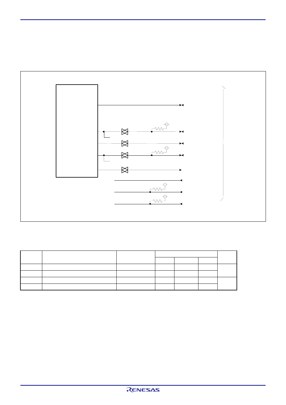
Figures 4.1 shows a connection diagram of the M3028BT-EPB. This connection diagram mainly shows the interface section.
The circuits not connected to the user system such as the emulator's control system are omitted. The signals not shown in
Figure 4.1 connect the evaluation MCU and the user system directly. Table 4.2 shows IC electric characteristics of this product
for reference purposes.
M16C/29
Evaluation MCU
P85/NMI#
P86/Xcout
P87/Xcin
CNVss
RESET#
Xin
Xout
510k
Ω
VCC
*
74HC4066
74HC4066
510k
Ω
VCC
510k
Ω
VCC
*
*
*
74HC4066
*: Connected to the inside of the emulator.
510k
Ω
VCC
*
74HC4066
Us
er sy
st
em
IC11
P00--P07
P10--P17
P20--P27
P30--P37
P60--P67
P70--P77
P80--P84
P90--P93, P95-- P97
P100-- P107
P86/Xcout
P87/Xcin
Xout
P85/NMI#
P00-- P07
P10-- P17
P20-- P27
P30-- P37
P60-- P67
P70-- P77
P80-- P84
P90-- P93, P95--P97
P100-- P107
Figure 4.1 Connection diagram (when using M3028BT-EPB)
Table 4.2 Electrical characteristics of the 74HC4066
Standard values
Symbol Item
Condition
Unit
Min. Standard
Max.
R
ON
ON
resistor
VCC=4.5V
-
96
200
ΔR
ON
ON
resistor
difference
VCC=4.5V - 10 -
Ω
I
OFF
Leak current (Off)
VCC=12.0V
-
-
±1
I
IZ
Leak current (On, output: open)
VCC=12.0V
-
-
±1
μA
Page 68 of 86