Adjusting the volume of each layer, Selecting the midi connector to use for output, Layer level slider – Roland RD-300 User Manual
Page 50: Using the rd-300nx as a master keyboard
52
Using the RD-300NX as a Master Keyboard
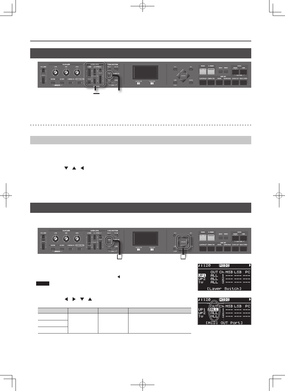
Adjusting the Volume of Each Layer
LAYER
LEVEL
Slider
[MIDI]
Button
When the [MIDI] button is lit, you can use the LAYER LEVEL Sliders to control the EXTERNAL Layer in the same way as with the Layer (p. 21).
LAYER LEVEL Slider
If the [MIDI] button is lit, these sliders adjust the volume of the EXTERNAL layers.
Selecting the Layer that You want to Sound ( Layer Switch)
Here’s how to turn each layer on/off .
1. Press the [MIDI] button so the “MIDI” indicator is lit .
The MIDI screen appears.
2. Use the Cursor [
] [
] [
] buttons to move the cursor to the layer name “UP1,” “UP2,” or “LW” (lowercase if the layer is off ) at
the far left of the fi rst page .
The selected layer name is highlighted.
3. Use the [INC] [DEC] buttons to turn the layer on/off .
If a layer is switched off , its name is shown in lowercase characters.
Selecting the MIDI Connector to Use for Output
The RD-300NX provides a MIDI OUT connector and a USB MIDI connector.
For each layer you can select the MIDI OUT connector or USB MIDI connector from which its data is to be transmitted.
1
2
1. Press the [MIDI] button so the “MIDI” indicator is lit .
The MIDI screen appears.
If the following screen doesn’t appear, press the Cursor [ ] button several times to display the MIDI screen.
NOTE
When Rec Mode is set to ON in the Utility Rec Setting in Edit mode, the MIDI screen as shown above is
not displayed. Set Rec Mode to OFF when setting the MIDI Transmit channel (p. 77).
2. Use the Cursor [
] [
] [
] [
] buttons to move the cursor, and use the [DEC] [INC]
buttons to specify the connector from which each layer will transmit its MIDI data .
Layer
Parameter
Settings
Description
UP 1 (UPPER 1)
OUT
(MIDI OUT Port)
ALL,
MIDI,
USB
The RD-300NX’s performance data is transmit-
ted from the selected connector.
UP 2 (UPPER 2)
LW (LOWER)