Traps: linkup and linkdown, Refer to, In appendix d – Paradyne 7612 SNMP DSU User Manual
Page 106
Standards Compliance for SNMP Traps
D-2
7612-A2-GB20-10
November 1997
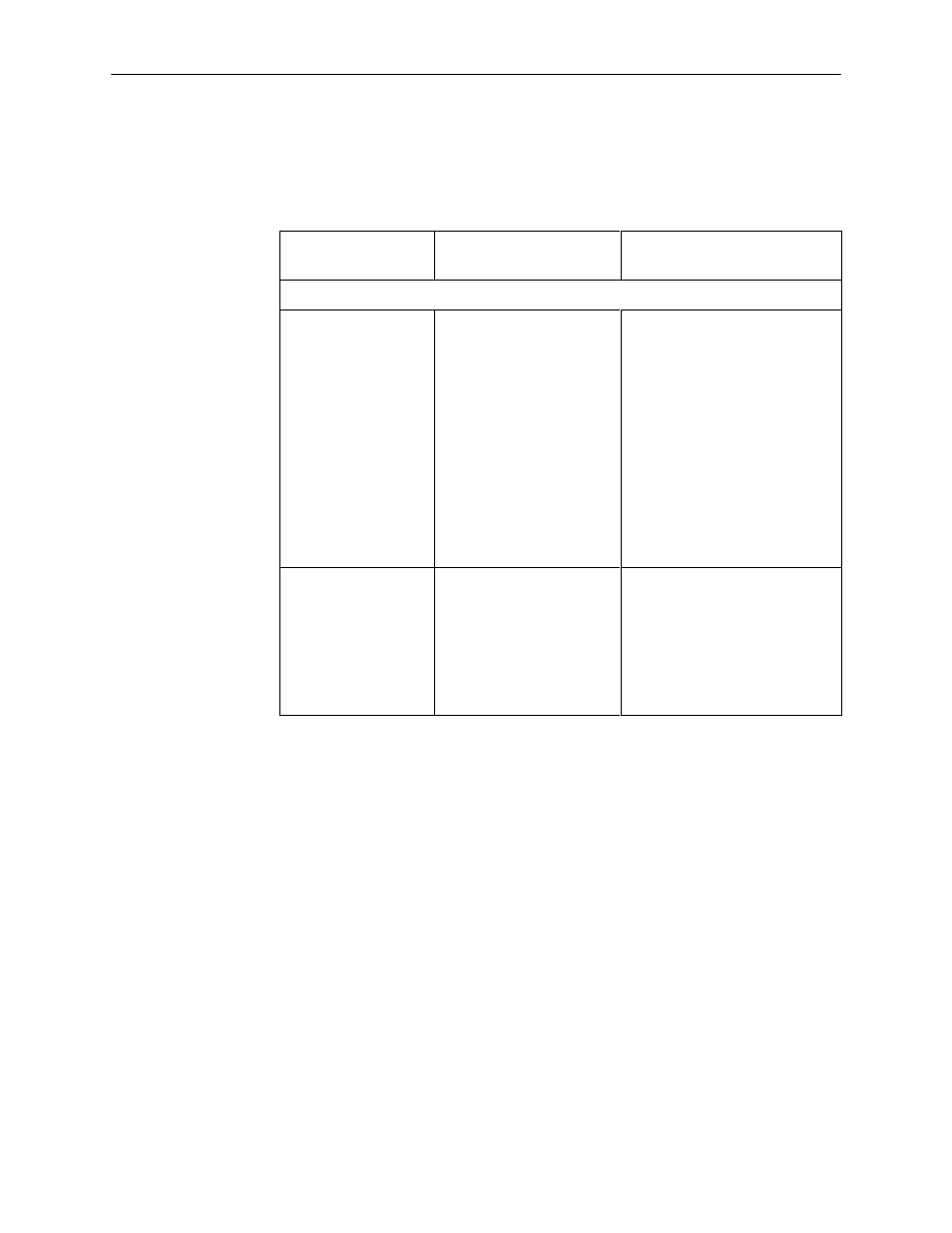
Traps: linkUp and linkDown
The following table describes the conditions that define linkUp and linkDown for
each interface:
Interface
linkUp/Down
Variable-Bindings
Possible Cause
Physical Sublayer – Represented by the entry in the MIB II Interfaces Table.
DDS network
(Supported by the
media-specific DDS
Enterprise MIB.)
H
ifIndex (RFC 1573)
H
ifAdminStatus
(RFC 1573)
H
ifOperStatus (RFC 1573)
H
i
fType (RFC 1573)
H
ddsStatus (DDS
Enterprise MIB)
H
linkDown – One or more
alarm conditions are active on
the interface.
Alarm conditions include:
– No Signal
– Out of Service
– Out of Frame
– Crossed Pair Detected
– In-band Framing Error
– Excessive Bipolar Violations
(BPVs)
H
linkUp – No alarms on the
interface.
Synchronous User
Data Port
(Supported by the
media-specific
RS232-Like MIB.)
H
ifIndex (RFC 1573)
H
ifAdminStatus
(RFC 1573)
H
ifOperStatus (RFC 1573)
H
i
fType (RFC 1573)
H
linkDown – The Alarm
condition active on the
interface is DTR Off . The DTR
alarm condition only generates
a linkUp/linkDown trap if the
DTE supports the DTR lead.
H
linkUp – No alarm on the
interface.