Maintenance – Lochinvar COPPER-FIN 497 - 2067 User Manual
Page 57
57
8
Maintenance
Listed below are items that must be checked to ensure safe,
reliable operations. Verify proper installation after servicing.
Label all wires prior to disconnection when
servicing controls. Wiring errors can cause
improper and dangerous operation.
ƽ CAUTION
Appliance area
Keep appliance area clear and free from combustible materials,
gasoline and other flammable vapors and liquids.
Water circulating pump
Inspect pump every six months and oil as necessary. Use SAE 30
non-detergent oil or lubricant specified by pump manufacturer.
Burner flames
Visually check main burner flames at each start up after long
shutdown periods or at least every six months. Burner viewports
are located on the right and left sides of the unit.
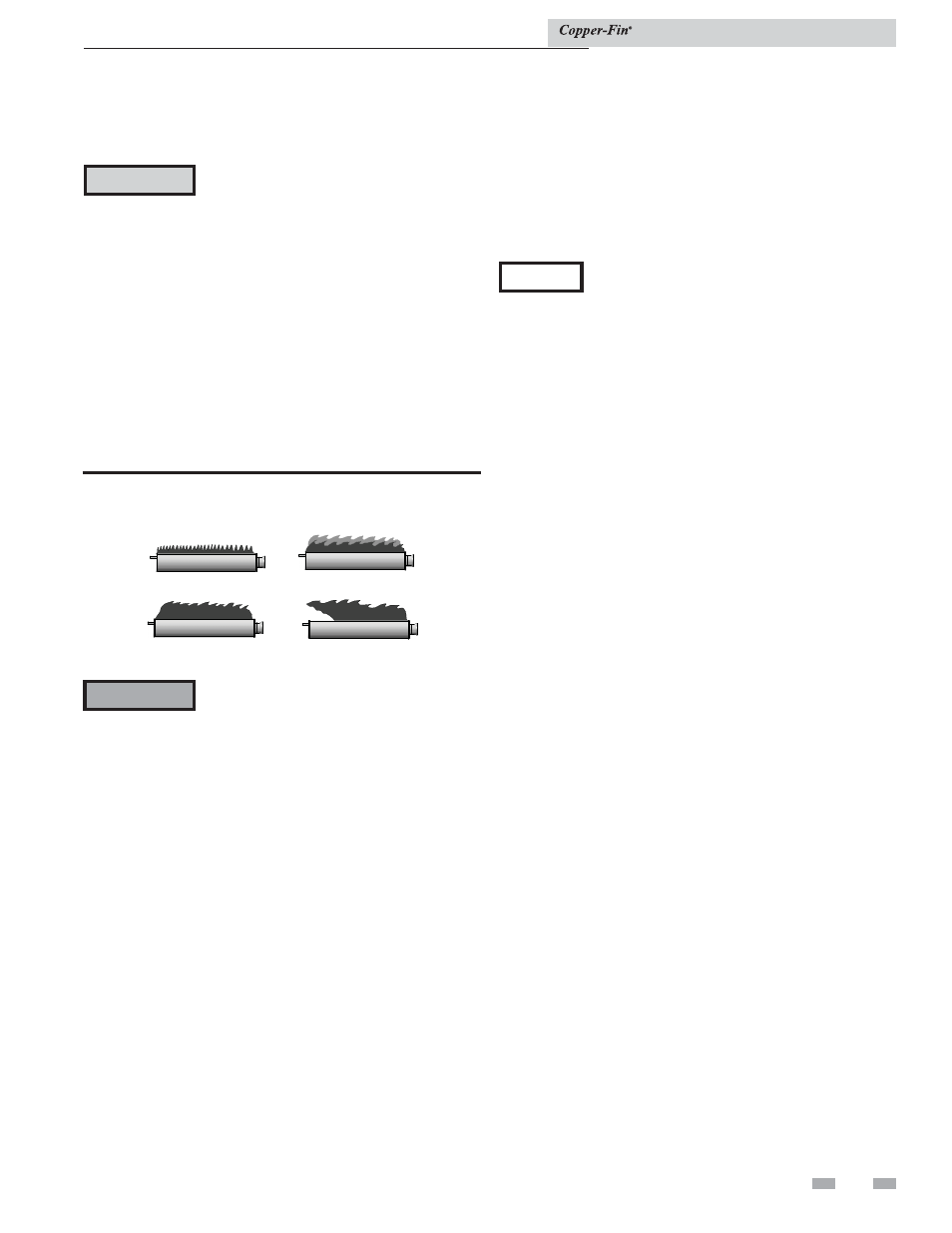
NORMAL
A
YELLOW TIP
B
D
FLAME LIFT
C
YELLOW FLAME
ƽ WARNING: The area around the burners is hot and direct contact could result in burns!
Figure 8-1_Flame patterns
The areas around the burner viewports
are hot. Direct contact with the unit could
result in burns.
ƽ WARNING
Normal Flame: A normal flame is blue with slight yellow tips,
has a well-defined inner cone, and displays no lifting flames.
Yellow Tips: The usual causes for yellow tips on the burner
flame are burner air flow blockage or partial obstruction.
Yellow Flames: The usual causes for yellow flames are primary
air flow blockage to the burner(s) or excessive gas input. Correct
this condition immediately.
Lifting Flames: The usual causes for lifting flames are over firing
the burner(s), excessive primary air, or high draft.
If you observe improper flame patterns, examine the venting
system, ensure proper gas supply, and ensure adequate supply
of combustion and ventilation air.
Flue gas passageways cleaning procedure
Any sign of soot around the outer jacket, at the burners or in the
areas between the fins on the copper heat exchanger indicates
a need for cleaning. The following cleaning procedures must
only be performed by a qualified serviceman or installer. Proper
service is required to maintain safe operation. Properly installed
and adjusted units seldom need flue cleaning.
NOTICE
All gaskets on disassembled components must
be replaced with new gaskets on reassembly.
Gasket kits are available from your distributor.
Burner removal and cleaning
1. Turn off main power to unit.
2. Turn off main manual gas shutoff to unit.
3. Remove the front outer jacket panels.
4. Disconnect manifold from gas train using union(s) just
below each gas valve(s).
5. Remove mounting screws from manifold mounting
brackets. Pull the manifold/orifice assembly away from
burners. Repeat for each manifold assembly.
6. Remove two mounting screws from burner and slide
burner out toward front of unit. Use caution to prevent
damage to burners, refractory, hot surface igniter or wiring.
7. Remove soot from burners with a stiff bristle brush.
Dirt may be removed from burner ports by rinsing the
burner thoroughly with water. Drain and dry burners
before re-installing. Damaged burners must be replaced.
When installed in a dusty and dirty location, the burners may
require cleaning on a 3 to 6 month schedule or as needed, based
on severity of contamination. Contaminants can be drawn in
with the combustion air. Non combustible particulate matter
such as dust, dirt, concrete dust or dry wall dust can block
burner ports and cause non-warrantable failure. The standard
inlet air filter will help eliminate dust and dirt from entering
the unit. Use extreme care when operating a unit for temporary
heat during new construction. The burners could require a
thorough cleaning before the unit is placed in service.
Installation & Service Manual