Gas connections, Connecting to gas supply, Gas pressure test – Lochinvar COPPER-FIN 497 - 2067 User Manual
Page 22: Gas piping
3
Gas connections
22
Connecting to gas supply
Verify that the appliance is supplied with the type of gas specified
on the rating plate. This appliance is configured for operation
up to 2000 feet altitude. Consult factory for installations above
2000 feet elevation.
Inlet gas pressure: Measured at the inlet pressure tap on the
appliance gas manifold. The pressure tap is located upstream of
the combination gas valve(s).
See Table 3A for maximum and minimum inlet pressures. Do
not exceed the maximum. Minimum inlet pressure is for the
purpose of input adjustment.
TABLE 3A
INLET GAS PRESSURE
MODEL
NATURAL
LP
Max.
w.c.
Min.
w.c.
Max.
w.c.
Min.
w.c.
497 - 747
14''
4.0''
14.0''
8.0''
987 - 2067
14''
4.5''
14.0''
8.0''
Manifold pressure: The gas regulator on the unit’s
combination gas valve is adjustable to supply proper manifold
pressure for normal operation.
Gas pressure test
1. The appliance must be disconnected from the gas
supply piping system during any pressure testing of that
system at a test pressure in excess of 1/2 PSIG (3.5 kPa).
2. The appliance must be isolated from the gas supply
piping system by closing a manual shutoff valve during
any pressure testing of the gas supply piping system at
test pressures equal to or less than 1/2 PSIG (3.5 kPa).
3. The appliance and its gas connection must be leak
tested before placing it in operation.
Gas piping
To safely operate this unit, you must properly size the gas
supply piping. See Tables 3B through 3D for piping and
fitting requirements. Gas pipe size may be larger than heater
connection.
The gas connection for Models 497 - 747 is 1 1/4'' NPT and on
Models 987 - 2067 the gas connection to these units is 2'' NPT.
For ease of service, install a union.
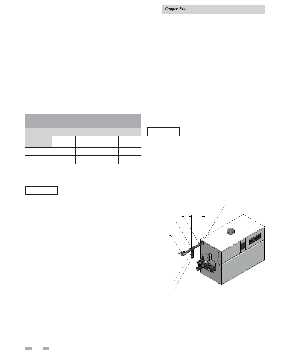
Figure 3-1_Gas line connection
CAP
NIPPLE
MANU
NUAL MAIN
SHUT OFF
VA
VALVE
UN
UNION
COUPLING
8"
8"
MIN
USE WRENC
NCH
TO HOLD
SUPPLY PIPE
NOTICE
It is the installer’s responsibility to supply
the sediment trap (drip leg).
The combination gas valves have an integral vent limiting
device and do not require venting to atmosphere, outside the
building. The unit will not operate properly if the reference hose
is removed or a vent to atmosphere is installed.
Optional gas controls may require routing of bleeds and vents
to the atmosphere, outside the building when required by local
codes.
Install a manual main gas shutoff valve, outside of the unit gas
connection within six feet of the unit in accordance with the
requirements of the National Fuel Gas Code, ANSI Z223.1.
You must provide a sediment trap (drip leg) in the inlet of the
gas connection to the unit.
Installation & Service Manual
NOTICE
If an inline high gas pressure regulator is
used, it MUST BE of the lockup type and
be located a minimum of 10 feet from the
appliance. Failure to do so may result in
insufficient gas volume supplied to the
appliance.
If you must adjust regulator pressure, follow the instructions
under Gas Manifold Pressure Adjustment on page 25. Do not
increase regulator pressure beyond specified pressure setting.