Electrical connections, Terminal strip connection options, Installation & service manual – Lochinvar COPPER-FIN 497 - 2067 User Manual
Page 38
38
5
Electrical connections
External EMS connection to terminal
strip for stage firing control of
burners
This unit is equipped with a factory installed terminal strip
for connection of an energy management system (EMS)
to the burner stages. The EMS terminal strip is located
in the unit’s control panel. Ensure that all wiring used
for connection to this terminal strip is properly sized per
the recommendations in TABLE 5A. When connecting
an EMS to this terminal strip to sequence on each stage
of burner operation, the unit’s internal thermostat or
electronic sequencer should be set as an additional high
limit control. This will prevent problems between the set
points of the EMS and the boiler’s internal controller.
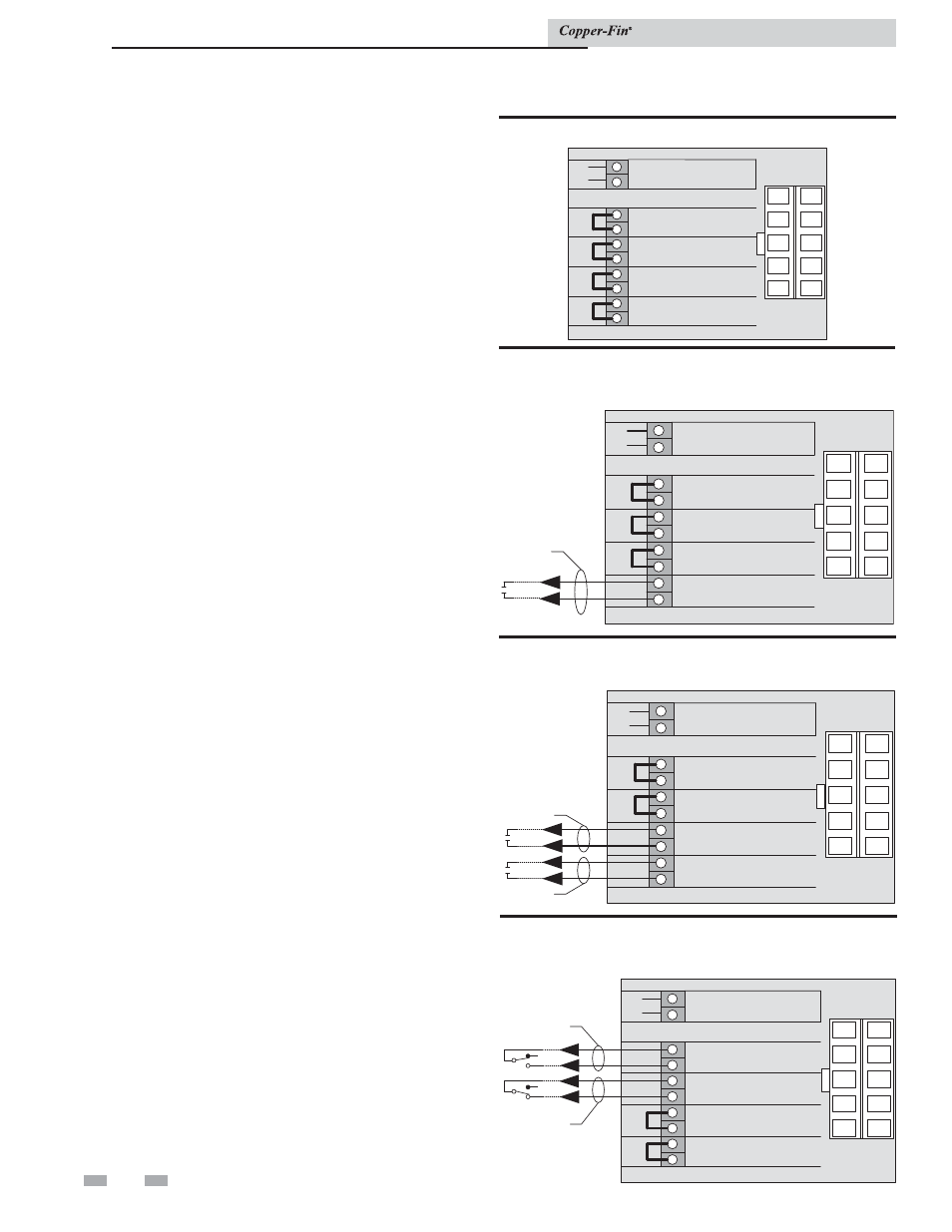
Terminal strip connection options
Figure 5-2 shows the position of jumpers as shipped from
the factory for stand-alone operation of boilers or water
heaters.
Figure 5-3 shows connections to the terminal strip for
Remote ON/OFF control of the boiler or water heater.
The 1C-1NO jumper must be removed when making
these wiring connections. This remote ON/OFF control
will provide an Enable/Disable signal to the unit and allow
the unit to operate based on the stage set points, until the
remote ON/OFF signal is cancelled.
Figure 5-4 shows the connections necessary to operate the
unit as a two-stage (High/Low Fire) boiler or water heater
from an Energy Management System (EMS). The actual
set point temperatures are controlled by the EMS. The
High Fire Offset on the electronic temperature control in
the unit must be set to zero and the set point must be set
to a value which will function as an upper limit for proper
operation under this two-stage control from an EMS.
Figure 5-5 shows the Continuous and Intermittent
terminals. External safety devices connected to these
terminals will function to protect the unit. Devices
connected to the Intermittent terminals (B1 and B2) are
monitored only when there is an active Call for Heat.
Devices connected to the Continuous terminals (A1
and A2) are monitored continuously and will activate
an alarm (if the unit is equipped with the alarm option)
anytime the safety device senses an abnormal condition.
1
2
3
4
5
6
7
8
9
10
+
+
+
+
+
+
+
+
+
+
SYSTEM/TANK
SENSOR
B2
B1
A2
A1
2 NO
2 C
1 NO
1 C
INTERMITTENT
LIMITS
CONTINUOUS
LIMITS
HIGH FIRE
ENABLE
LOW FIRE
ENABLE
9
8
7
6
4
3
2
1
10
5
1
2
3
4
5
6
7
8
9
10
+
+
+
+
+
+
+
+
+
+
SYSTEM/TANK
SENSOR
B2
B1
A2
A1
2 NO
2 C
1 NO
1 C
INTERMITTENT
LIMITS
CONTINUOUS
LIMITS
HIGH FIRE
ENABLE
LOW FIRE
ENABLE
9
8
7
6
4
3
2
1
10
5
Remote
on/off
Stage 1
1
2
3
4
5
6
7
8
9
10
+
+
+
+
+
+
+
+
+
+
SYSTEM/TANK
SENSOR
B2
B1
A2
A1
2 NO
2 C
1 NO
1 C
INTERMITTENT
LIMITS
CONTINUOUS
LIMITS
HIGH FIRE
ENABLE
LOW FIRE
ENABLE
9
8
7
6
4
3
2
1
10
5
Stage 2
Continuous
Alarms
1
2
3
4
5
6
7
8
9
10
+
+
+
+
+
+
+
+
+
+
SYSTEM/TANK
SENSOR
B2
B1
A2
A1
2 NO
2 C
1 NO
1 C
INTERMITTENT
LIMITS
CONTINUOUS
LIMITS
HIGH FIRE
ENABLE
LOW FIRE
ENABLE
9
8
7
6
4
3
2
1
10
5
Intermittent
Alarms
Figure 5-2_Stand-alone operation
Figure 5-5_Field installation safety devices
Figure 5-4_Two-stage (high/low fire) boiler or water
heater
Figure 5-3_Remote on/off boiler or water heater
Installation & Service Manual