Gas connections – Lochinvar COPPER-FIN 497 - 2067 User Manual
Page 26
3
Gas connections
26
12.
If adjustment is necessary, remove the regulator
cover screw on the gas valve. Note: If the gas valve
under adjustment is located on a manifold assembly
monitored by an igniter, the unit may shut down and
recycle when the regulator cover screw is removed.
This is normal.
13.
Turn the regulator adjustment screw “clockwise” to
raise the regulator gas pressure. Turn the regulator
adjustment screw “counterclockwise” to lower the
regulator gas pressure.
14.
Replace the regulator cover screw and make sure it is
tight for proper operation.
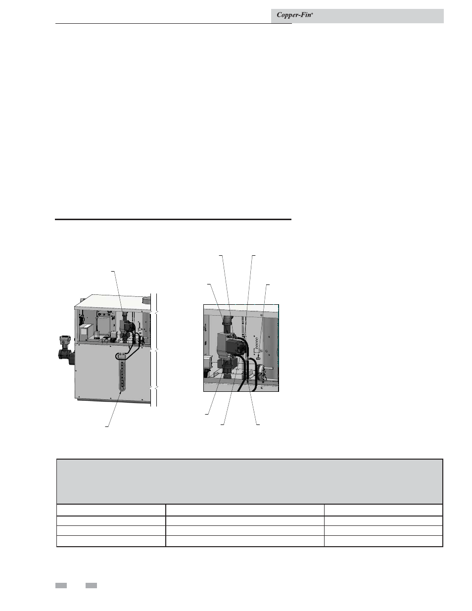
PRESSURE
REGULATOR
ADJUSTMENT
(UNDER CAP
SCREW)
INLET
OUTLET
GAS
VALVE
CONTROL
KNOB
MANOMETER
MANIFOLD
PRESSURE
CHAMBER
PRESSURE
TEE
TO BARBED
FITTING
Figure 3-4_Measuring manifold gas pressure
TABLE 3E
Net Manifold Pressure
Regulator Pressure Less
Front Chamber Pressure
MODEL
Nat. Gas
LP
497 - 747
1.8'' w.c.
--
987 - 2067
1.2'' w.c.
--
497-2067
--
4.6'' w.c.
Installation & Service Manual
15. Read the value on the manometer/magnahelic and
compare it to the values in TABLE- 3E.
16. Repeat this adjustment procedure for each gas valve as
necessary to adjust to the proper manifold gas pressure.
17. Remove hoses, replace and tighten plugs and caps
when
complete.
18. Replace top front upper jacket access panels and
control panel door in reverse order.
19. If proper ignition and burner operation is not
achieved after checking gas supply pressure, see
Cleaning and Maintenance, page 58 for Combustion
Air Fan Adjustment. Follow the procedure to adjust
the combustion air fans as necessary.