Determine unit location – Lochinvar COPPER-FIN 497 - 2067 User Manual
Page 10
10
1
Determine unit location
Locating the unit
1. Maintain all clearances from combustible construction
when locating unit. See Clearances from Combustible
Construction, this page.
2. Locate the unit so that if water connections should
leak, water damage will not occur. When such locations
cannot be avoided, install a suitable drain pan that
is well-drained under the unit. The pan must not
restrict combustion air flow. The appliance
manufacturer is not responsible for water damage in
connection with this unit, or any of its components.
3.
Install indoor units so that the ignition system
components are protected from any water while
operating or during service.
4.
Appliances located in a residential garage and in
adjacent spaces that open to the garage and are not
part of the living space of a dwelling unit must be
installed so that all burners and burner ignition devices
have a minimum clearance of not less
than 18'' (46cm) above the floor. The
appliance must be located or protected so that it is
not subject to physical damage by a moving vehicle.
5. DO NOT install this appliance in any location where
gasoline or flammable vapors are likely to be present.
6. The appliance must be installed on a level surface.
7. Models 497 - 747 are approved for installation on
combustible flooring using the approved combustible floor
kits (reference Table 1A). Models 987 - 2067 are approved
for installation on combustible flooring. Do not install
appliances directly on carpeting.
8. For outdoor models, you must install an optional vent
kit. Instructions for mounting the vent kit are included
in the venting section. Do not install outdoor models
directly on the ground. You must install the outdoor
unit on a concrete, brick, block, or other
non-combustible pad. Outdoor models have additional
special location and clearance requirements. See
Outdoor Installation Venting, page 20. A wind proof
cabinet protects the unit from weather.
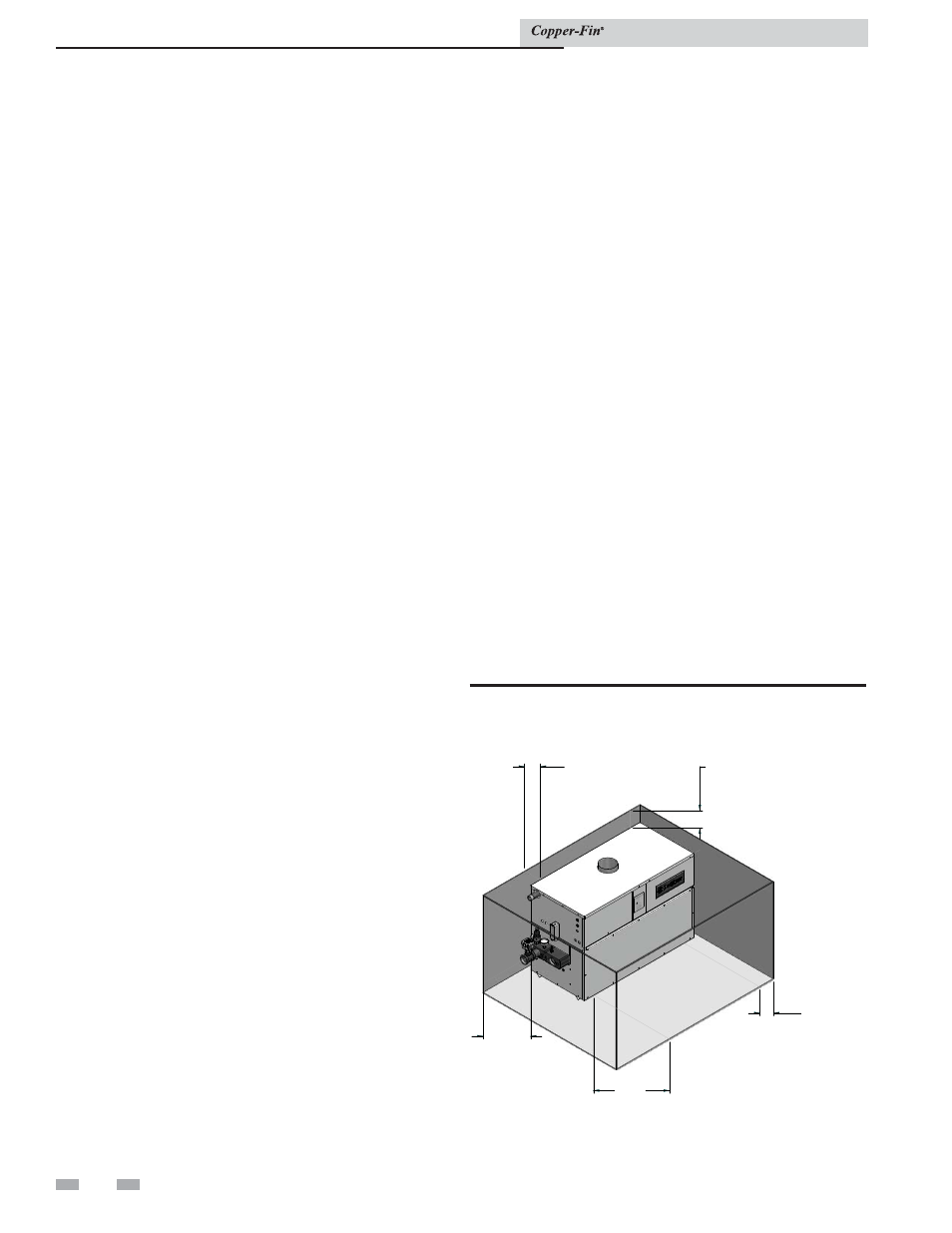
Indoor clearances from combustible
construction
Maintain minimum specified clearances for adequate
operation. Allow sufficient space for servicing pipe
connections, pump and other auxiliary equipment, as well
as the unit. See rating plate for specific service clearance
requirements.
Right Side
3'' (7.5 cm)
Rear
3'' (7.5 cm) (3'' min. from any surface)*
Left Side
6'' (15 cm) (24'' (0.61 m) suggested for
service)
Front
Alcove* (30'' (0.76m) suggested for service)
Top
3'' (7.5 cm)
Flue
1'' (25.4 mm)
Hot Water Pipes 1'' (25.4 mm)
*An Alcove is a closet without a door. Thirty-six inches (36")
to rear required for outdoor installation.
Note: No additional clearance is needed on the right side
of the unit for the observation port. An observation port is
located on both the right and left side of the unit.
Figure 1-1_Indoor clearances from combustible
construction
Installation
This unit meets the safe lighting performance criteria with the
gas manifold and control assembly provided, as specifi ed in the
ANSI standards for gas-fi red units. ANSI Z21.13/CSA 4.9 and
ANSI Z21.10.3/CSA 4.3.
3"
MIN
REAR
3"
MIN
RIGHT SIDE
30"
MIN
FRONT
3"
MIN
TOP
6"
MIN
LEFT SIDE
Installation & Service Manual