Electrical connections – Lochinvar COPPER-FIN 497 - 2067 User Manual
Page 44
44
5
Electrical connections
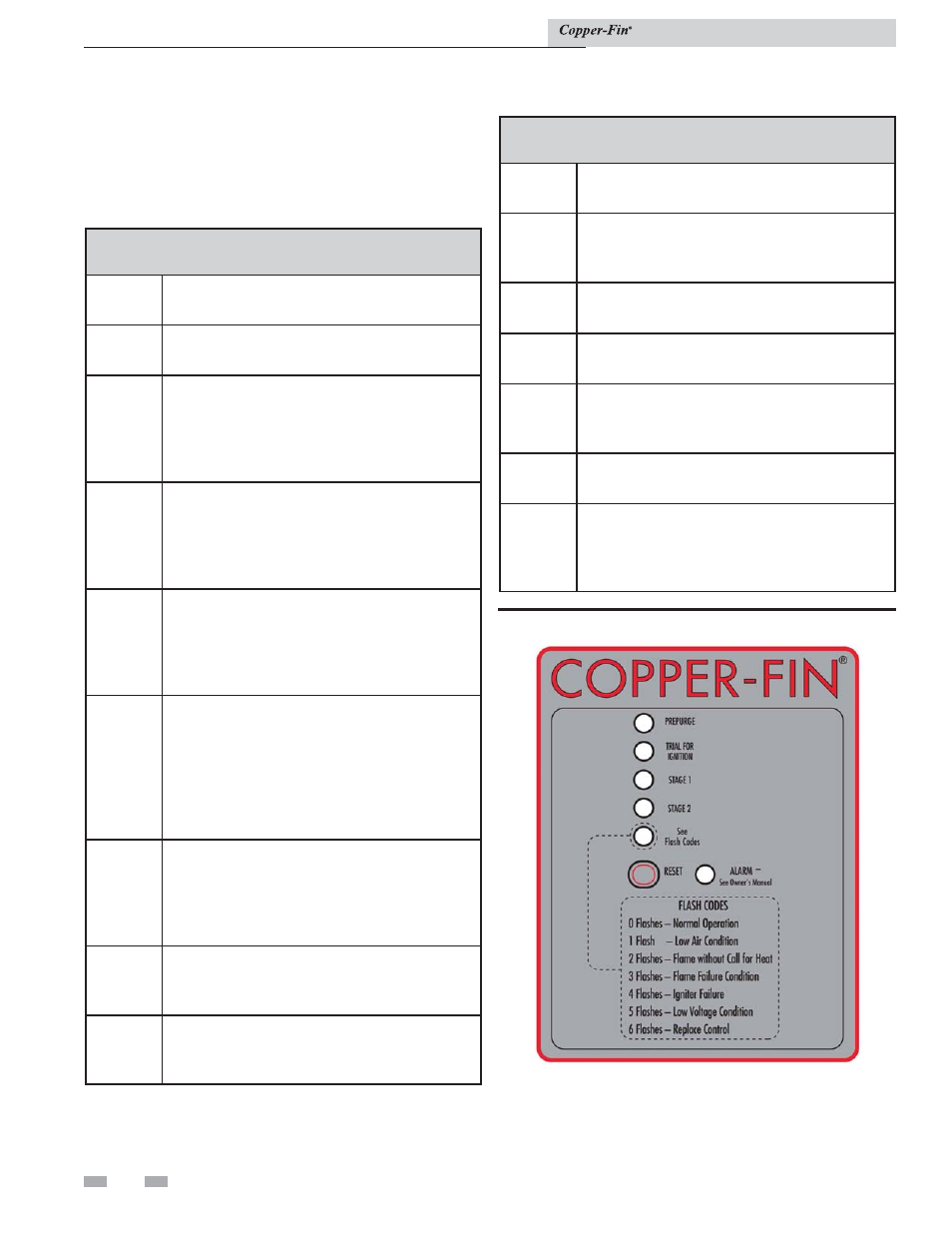
Operation and diagnostic lights
The diagnostic control panel has up to 6 indicating and
diagnostic lights to show all major steps of operation and
control sensed malfunctions. This panel is located on the front
of the unit.
TABLE 5D
Status LED Diagnostic Codes
Code
Sequence
Condition
Constant
ON
System OK, no faults present.
Constant
OFF
Possible control fault, check power; LED may
be defective, do not replace control if all
operational sequences function properly, see
Trouble- Shooting Guide.
One
Flash
Low Air, check air pressure switch and hoses
to pressure sensing points, fan, venting and
sealing of pressurized chamber. Note: Brief
flashing normal on fan start-up proving.
Two
Flashes
Flame without call for heat, check for a gas
valve stuck in the open position, air, venting,
burners and the combustion process. Fan will
remain on.
Three
Flashes
Lockout due to flame failure, push reset
button on the diagnostic panel after correcting
ignition problem. Initial heater start up
without properly bleeding air from the gas
line may require multiple reset functions to
achieve proper ignition.
Four
Flashes
Igniter failure, igniter will not maintain a
minimum 2.75 amp current draw, caused
by low voltage, bad wiring/continuity, high
resistance or igniter failure.
Five
Flashes
Power supply problem, check for low supply
voltage or transformer output less than 18VAC.
Six
Flashes
Replace ignition module, internal fault.
TABLE 5E
Status LED Diagnostic Codes
Code
Sequence
Condition Lights
Prepurge
Operation for combustion air fan before ignition
on stages 1 and 2.
Trial for
Ignition
Hot surface igniter preparing to light burners.
Stage 1 ON
Burners for stage 1 operating.
Stage 2 ON
Burners for stage 2 operating.
Status
Remote status light for ignition module.
Alarm
Indicates flame failure on the ignition module
and will indicate additional alarms if the alarm
of any failure option is purchased.
Figure 5-13_Operation / diagnostic lights
Installation & Service Manual