Domestic water heaters – Lochinvar COPPER-FIN 497 - 2067 User Manual
Page 48
48
7
Domestic water heaters
This section applies only to those units used to supply potable hot water for domestic use. The water heater must be installed
with a storage tank.
This section contains specific instructions for those units used to supply domestic hot water. All warnings, cautions, notes
and instructions in the general installation and service sections apply to these instructions. Water heaters are designed for
installation with a properly sized storage tank. The use of a properly sized pump and the control of water velocity, as explained
below, are important for correct operation of your water heater.
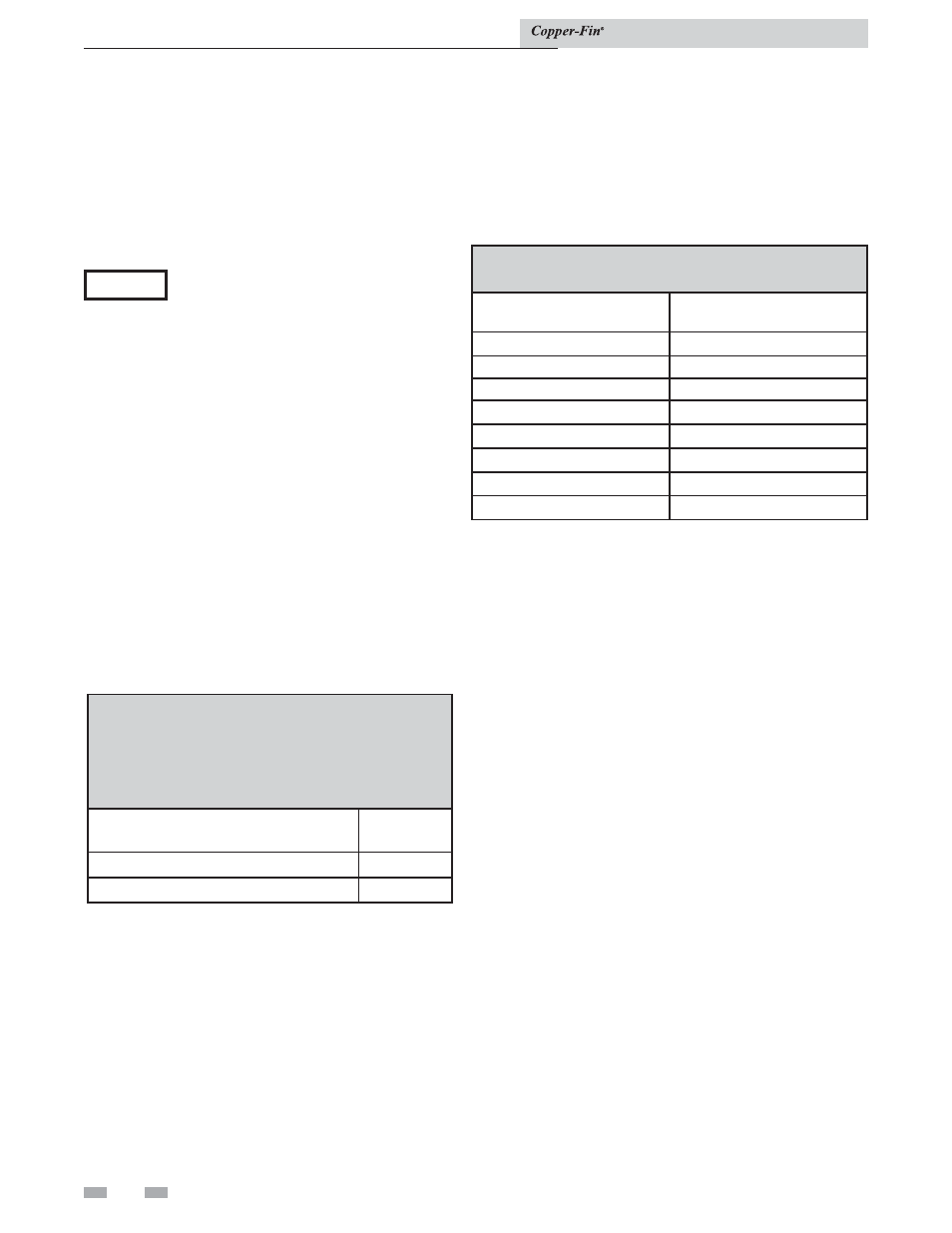
TABLE 7B
Temperature Rise Chart
Model
Temperature
Rise
497
15°F
647
19°F
747
22°F
987
18°F
1257
23°F
1437
26°F
1797
32°F
2067
37°F
Water velocity control
NOTICE
To ensure proper velocity through the
heat exchanger, you must regulate the
temperature rise across the heat exchanger
from inlet to outlet. Do this upon initial
installation and periodically recheck.
The correct temperature rise across the
heat exchanger ensures proper velocity
in the tubes. This will yield long life and
economical operation from your hot water
heater. Excessive lime build up in the
tube is caused by too low velocity through
the tubes. Excessive pitting or erosion in
the tube is caused by too high velocity
through the tubes. Take care to measure
temperature rise and maintain a velocity
as follows:
1. With the pump running and the water heater off,
the inlet and outlet thermometers should read the same
temperatures. If they do not, an adjustment must be
made to your final calculation.
2. Turn the water heater “On” and allow time for the
temperature to stabilize. Record the difference between
the inlet and outlet temperatures. This difference will
be the “temperature rise”.
3. Compare the temperature rise on the heater with the
required temperature rise in Table 7B. Should
adjustment be needed, proceed as follows:
If the temperature rise is too high, the water velocity is too
low. Check the following:
1. Check for restrictions in the outlet of the water heater.
2. Be sure all valves are open between the water heater and
the
tank.
3. Check the pump to be sure it is running properly and
that the pump motor is running in the proper direction
(see arrow on volute housing).
4. Be sure the installed circulation pipes between the
water heater and storage tank are not less than 2 1/2'' in
diameter on Models 987 - 2067.
5. Common manifold piping for multiple unit installations
will require larger minimum pipe sizes and tank
circulating tappings to ensure proper flow. See Table
7C on page 53.
If the temperature rise is too low, the water velocity is too
high. Adjust as follows:
1. Slowly throttle the valve on the outlet side of the water
heater until the temperature rise is steady at the required
temperature rise as noted in Table 7A.
2. Sustained high water velocity and low temperature rise
may result in pitting or erosion of the copper tubes in the
heat exchanger. This is a non-warrantable failure.
Temperature rise must be properly adjusted to achieve the
specified flow rate.
Installation & Service Manual
Initial set-up of maximum water flow
On initial start-up, the maximum water flow through
the heat exchanger must be manually set before normal
operation begins.
If higher flow rates are required through the water heater,
an optional Cupro Nickel heat exchanger is available.
Consult the factory for specific application requirements.
The heat exchanger is capable of operating within the design
flow rates required for the water heater, storage tank(s), and
connecting piping. Erosion of the finned copper tubes may
occur if the flow rate exceeds the maximum allowable flow
rate through the water heater. The maximum flow rate
through the water heater must be adjusted. Maximum
flow on Models 497 - 747 is 55 GPM and 90 GPM on Models
987 - 2067. Flow rate can be determined by measuring the
temperature rise through the water heater when it is firing
at full rate input.
TABLE - 7A
MAXIMUM WATER FLOW
ƽ CAUTION: The maximum flow rate through a water
heater with a copper heat exchanger must be set to provide
and not exceed the following flow:
Model
Maximum
Flow
497, 647, and 747
55 GPM
987, 1257, 1437, 1797, and 2067
90 GPM