Determine unit location, Table 1b – Lochinvar COPPER-FIN 497 - 2067 User Manual
Page 12
12
1
Determine unit location
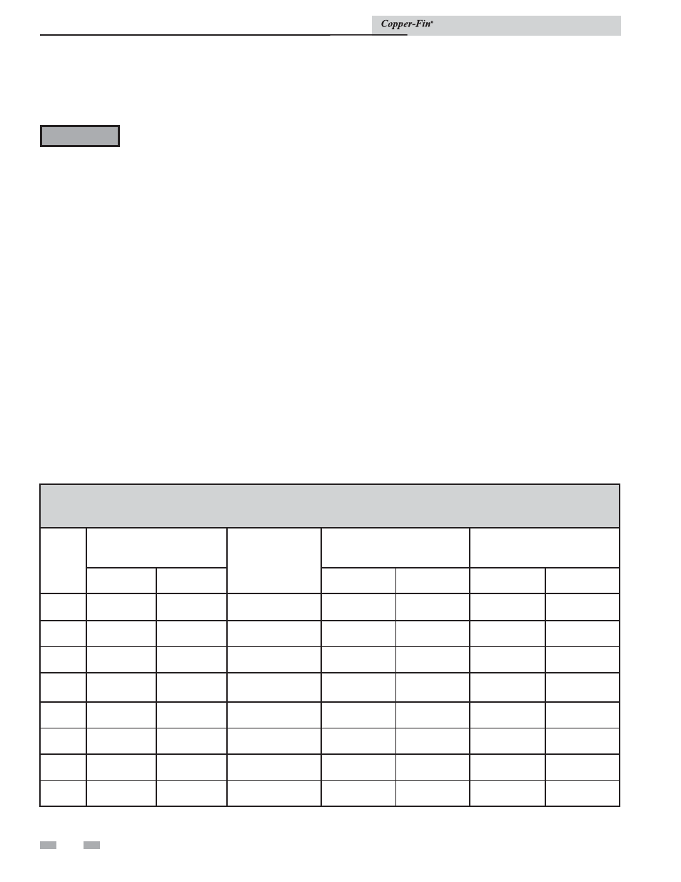
TABLE 1B
MINIMUM RECOMMENDED COMBUSTION
AIR SUPPLY TO EQUIPMENT ROOM
Model
Number
*Outside Air from
2 Openings Directly from
Outdoors
*Outside Air from
1 Opening Directly
from Outdoors, in
2
Inside Air from
2 Ducts Delivered from
Outdoors
Inside Air from
2 Ducts Delivered from Interior
Space
Top
Opening, in
2
Bottom
Opening, in
2
Top
Opening, in
2
Bottom
Opening, in
2
Top
Opening, in
2
Bottom
Opening, in
2
497
125
(806 cm
2
)
125
(806 cm
2
)
167
(1077 cm
2
)
250
(1613 cm
2
)
250
(1613 cm
2
)
500
(3226 cm
2
)
500
(3226 cm
2
)
647
163
(1052 cm
2
)
163
(1052 cm
2
)
217
(1400 cm
2
)
325
(2097 cm
2
)
325
(2097 cm
2
)
650
(4194 cm
2
)
650
(4194 cm
2
)
747
188
(1213 cm
2
)
188
(1213 cm
2
)
250
(1613 cm
2
)
375
(2420 cm
2
)
375
(2420 cm
2
)
750
(4839 cm
2
)
750
(4839 cm
2
)
987
248
(1600 cm
2
)
248
(1600 cm
2
)
330
(2129 cm
2
)
495
(3194 cm
2
)
495
(3194 cm
2
)
990
(6388 cm
2
)
990
(6388 cm
2
)
1257
315
(2032 cm
2
)
315
(2032 cm
2
)
420
(2710 cm
2
)
630
(4065 cm
2
)
630
(4065 cm
2
)
1260
(8130 cm
2
)
1260
(8130 cm
2
)
1437
360
(2323 cm
2
)
360
(2323 cm
2
)
480
(3097 cm
2
)
720
(4646 cm
2
)
720
(4646 cm
2
)
1440
(9291 cm
2
)
1440
(9291 cm
2
)
1797
450
(2903 cm
2
)
450
(2903 cm
2
)
600
(3871 cm
2
)
900
(5807 cm
2
)
900
(5807 cm
2
)
1800
(11614 cm
2
)
1800
(11614 cm
2
)
2067
518
(3342 cm
2
)
518
(3342 cm
2
)
690
(4452 cm
2
)
1035
(6678 cm
2
)
1035
(6678 cm
2
)
2070
(13356 cm
2
)
2070
(13356 cm
2
)
*Outside air openings shall directly communicate with the
outdoors. When combustion air is drawn from the outside
through a duct, the net free area of each of the two openings
must have twice (2 times) the free area required for Outside
Air/2 Openings. The above requirements are for the boiler
only; additional gas fired appliances in the equipment room
will require an increase in the net free area to supply adequate
combustion air for all appliances.
1.
Use only properly diluted inhibited glycol
anti-freeze designed for hydronic systems. Inhibited
propylene glycol is recommended for systems where
incidental contact with drinking water is possible.
2.
A solution of 50% antifreeze will provide
maximum protection of approximately -30°F.
3.
Follow the instructions from the antifreeze
manufacturer. Quantity of antifreeze required is
based on total system volume including
expansion tank volume.
4.
Glycol is denser than water and changes
the viscosity of the system. The addition
of glycol will decrease heat transfer and
increase frictional loss in the boiler and
related piping. A larger pump with more
capacity (15% to 25% more) may be required
to maintain desired fl
ow rates and
prevent a noise problem in a glycol system.
5.
Local codes may require a back fl ow preventer or
actual disconnect from city water supply when
antifreeze is added to the system.
Freeze Protection for a Heating Boiler
System (if required)
ƽ WARNING
Do not use undiluted or automotive type
anti-freeze.
Combustion and Ventilation Air
Provisions for combustion and ventilation air must be
in accordance with Section 5.3, Air for Combustion and
Ventilation, of the latest edition of the National Fuel Gas Code,
ANSI Z223.1, in Canada, the latest edition of CAN/CGA-B149
Installation Code for Gas Burning Appliances and Equipment,
or applicable provisions of the local building codes.
Provide properly-sized openings to the equipment room to
assure adequate combustion air and proper ventilation when
the unit is installed with conventional venting or sidewall
venting.
Installation & Service Manual