Electrical connections – Lochinvar COPPER-FIN 497 - 2067 User Manual
Page 43
43
5
Electrical connections
(continued)
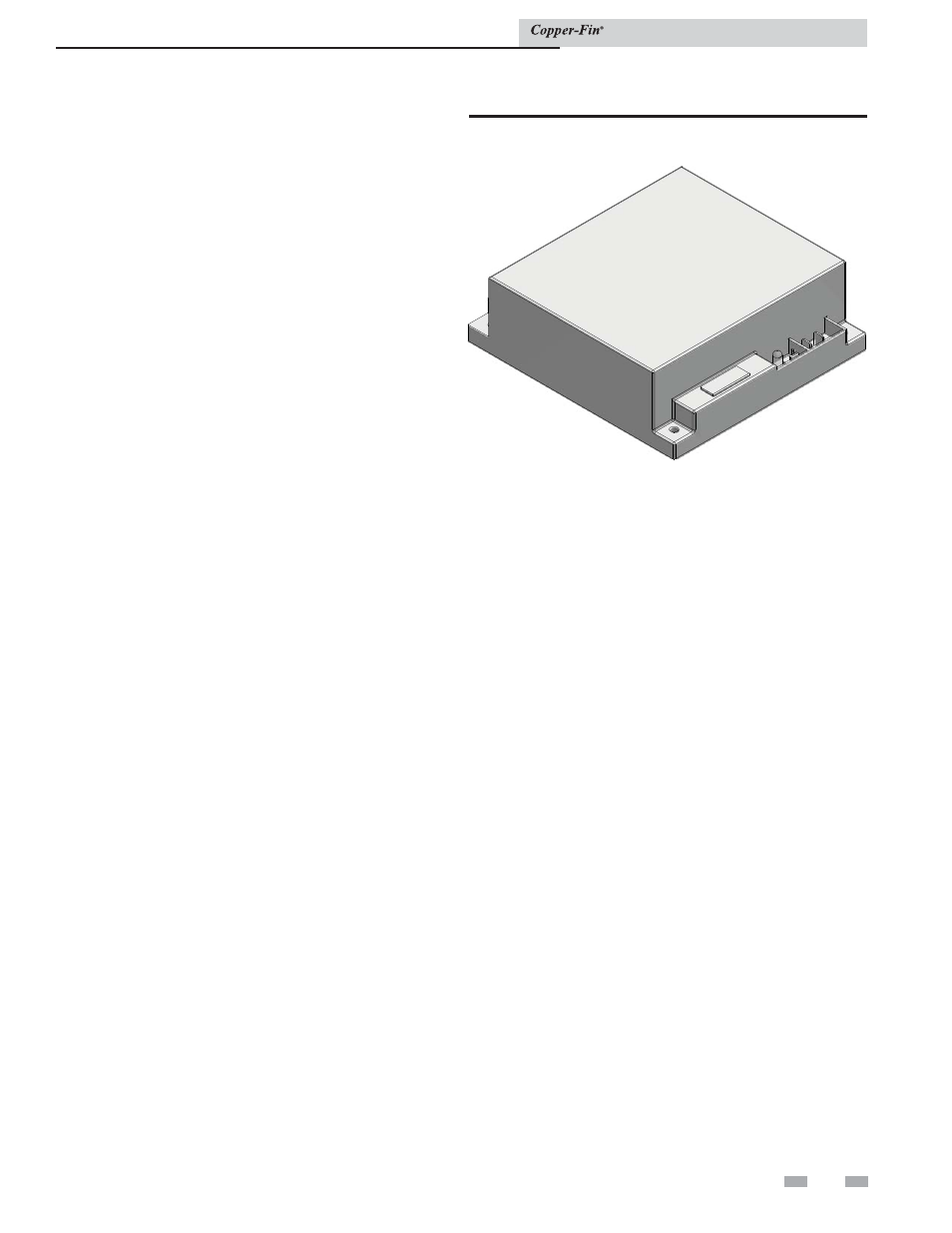
Diagnostic Status Indication
The ignition module has an LED which indicates the status of the
safety circuits. A remote Ignition Module Status indicating light
is wired from the ignition module Status LED and mounted on
the front diagnostic panel. The flashing operation of this light
indicates the diagnostic status of the ignition control module.
The status LED, mounted on the ignition module flashes a code
sequence from the Ignition Module to indicate the status of the
ignition process. See Table 5D for the flashing diagnostic status
codes as signaled by the ignition module.
Figure 5-12_Hot surface ignition control module
Ignition and control timings
Proven Pilot Hot Surface Ignition System is standard on all
models.
Hot Surface Ignition Module Timings (Nominal)
Prepurge:
15
Seconds
Hot Surface Igniter Heat-up Time:
25- 35 seconds
Main Burner Flame Establishing Period:
4
Seconds
Failure Response Time:
0.8 Seconds at less than 0.5 µA flame current
Flame Current:
2 - 6 µA
Time Delay Between Stages 1&2:
10 or 120 Seconds (depending on high fire offset settings)
Post-purge:
30
Seconds
Pump Delay Timing:
30 Seconds after burner shutdown.
Installation & Service Manual