Venting – Lochinvar COPPER-FIN 497 - 2067 User Manual
Page 18
2
Venting
18
1. Conventional negative draft
venting
NOTICE
Before installing a venting system, follow
all venting clearances and requirements
found in the Venting, General Information
section, page 16.
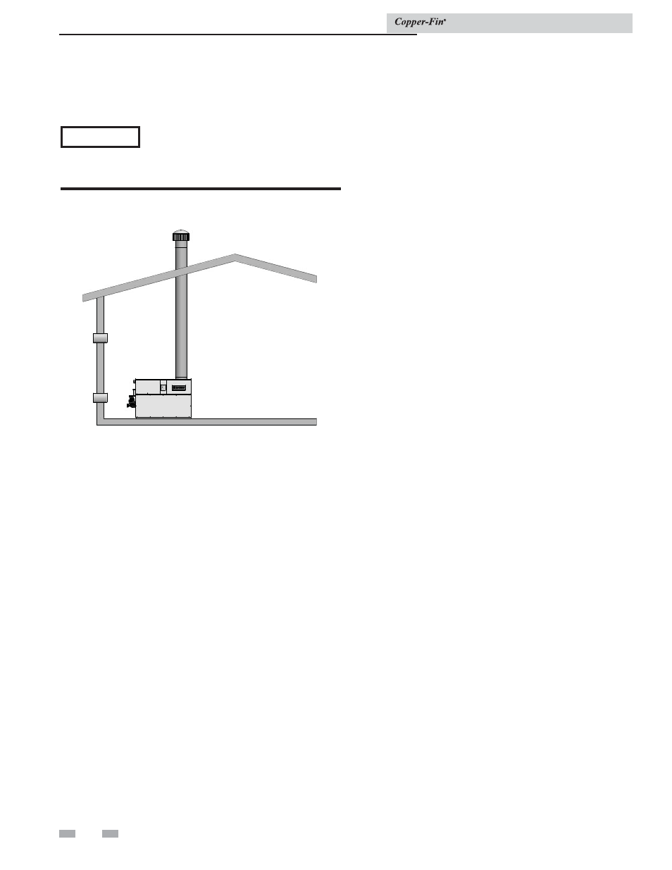
Figure 2-5_Conventional negative draft vertical venting
with combustion air louvers
This option uses Type-B double-wall flue outlet piping. The
blower brings in combustion air. The buoyancy of the heated
flue products causes them to rise up through the flue pipes. The
flue outlet terminates at the rooftop.
Negative draft
The negative draft in a conventional vent installation must be
within the range of 0.02 to 0.08 inches w.c. to ensure proper
operation. Make all draft readings while the unit is in stable
operation (approximately 2 to 5 minutes).
Connect the flue vent directly to the flue outlet opening on
the top of the unit. No additional draft diverter or barometric
damper is needed on single unit installations with a dedicated
stack and a negative draft within the specified range of 0.02 to
0.08 inches w.c. If the draft in a dedicated stack for a single unit
installation exceeds the maximum specified draft, you must
install a barometric damper to control draft. Multiple unit
installations with combined venting or common venting with
other Category I negative draft appliances require each boiler
to have a barometric damper installed to regulate draft within
the proper range.
Do not connect vent connectors serving appliances vented by
natural draft (negative draft) to any portion of a mechanical
draft system operating under positive pressure. Connecting to a
positive pressure stack may cause flue products to be discharged
into the living space causing serious health injury.
Flue outlet piping
The negative draft in a conventional vent installation must be
within the range of 0.02 to 0.08 inches w.c. to ensure proper
operation. Make all draft readings while the unit is in stable
operation (approximately 2 to 5 minutes).
Connect the flue vent directly to the flue outlet opening on
the top of the unit. No additional draft diverter or barometric
damper is needed on single unit installations with a dedicated
stack and a negative draft within the specified range of 0.02 to
0.08 inches w.c.
You can combine the flue with the vent from any other negative
draft, Category I appliance. Using common venting for multiple
negative draft appliances requires you to install a barometric
damper with each unit. This will regulate draft within the
proper range. You must size the common vent and connectors
from multiple units per the venting tables for Type-B double-
wall vents in the latest edition of the National Fuel Gas Code,
ANSI Z223.1 and/or CAN/CGA-B149 Installation Code.
Common venting systems may be too large when an existing
unit is removed.
Common venting systems
Installation & Service Manual