Electrical connections, Temperature control sensors, Inlet water temperature sensor – Lochinvar COPPER-FIN 497 - 2067 User Manual
Page 41: Multi-purpose temperature sensor, Outdoor air temperature sensor, Boiler application, Water heater application, Placement of sensors inlet temperature sensor, System sensor, Tank sensor
41
5
Electrical connections
(continued)
Temperature control sensors
This is a two-stage temperature control that controls the
burner ignition, pump, and alarm functions. This temperature
controller can measure up to three different sensor inputs,
depending upon how the unit is set up. They are as follows:
1. Inlet Water Temperature Sensor
2. Multi-Purpose Temperature Sensor
3. Outside Air Temperature Sensor
Inlet water temperature sensor
This sensor measures the inlet water temperature coming into
the unit.
Multi-purpose temperature sensor
This sensor can be used as a system sensor or a tank sensor.
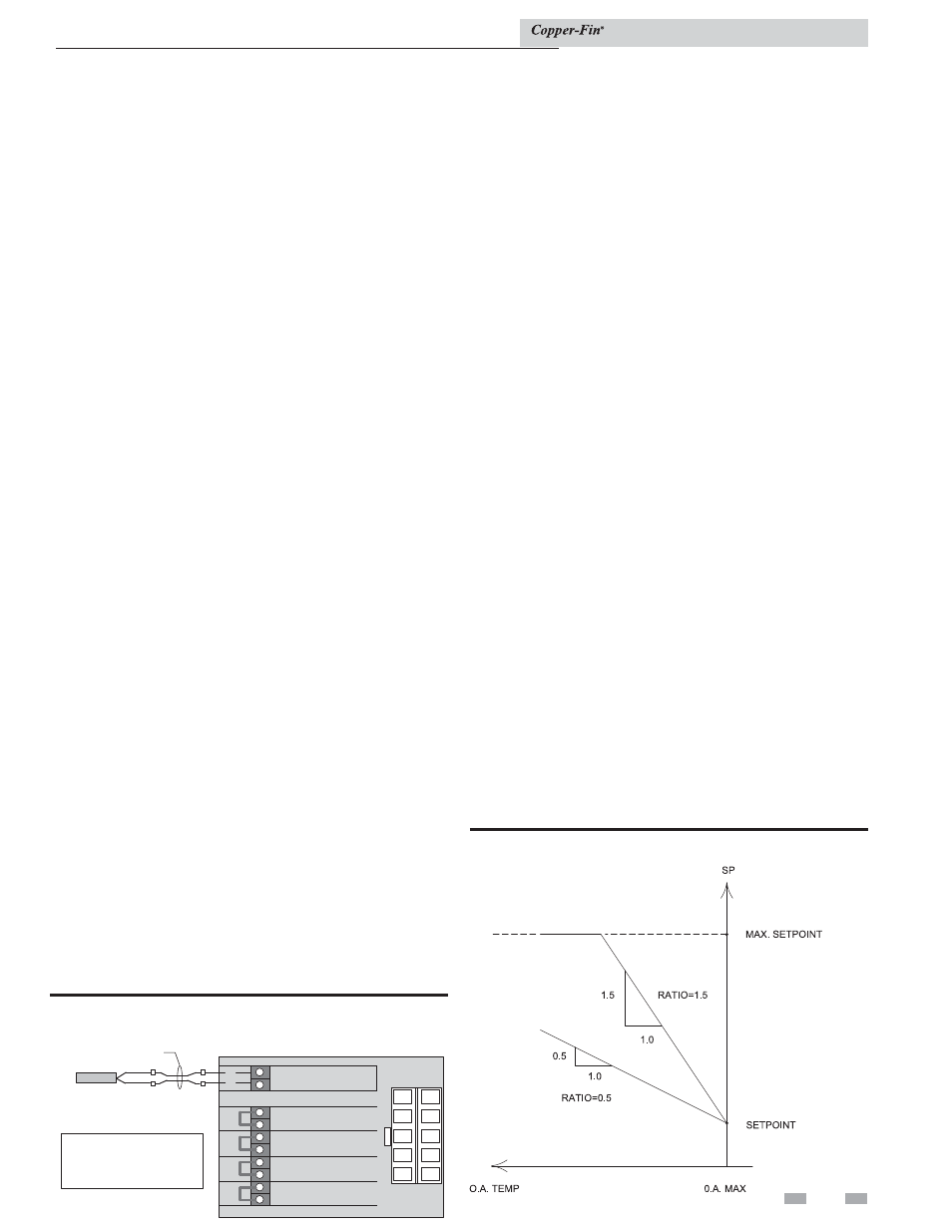
Outdoor air temperature sensor
This sensor is only available on boiler units with an outdoor
air reset option. This allows you to tie boiler operation to
the outdoor air temperature. As outside temperatures drop,
the control will increase the temperature setting of the boiler.
As outdoor temperatures rise, the control will decrease the
temperature to the selected set point of the boiler. You can set
the control to shut the boiler off when a desired outdoor air
temperature level is reached.
Boiler application
Standard boiler units are shipped with two sensors; the inlet
water temperature sensor and the multi-purpose temperature
sensor. The multi-purpose sensor should be used as a system
sensor. Boilers with the outdoor air reset option also have an
outside air temperature sensor.
Water heater application
Water heater units are shipped with two sensors; the inlet water
temperature sensor and the multi-purpose temperature sensor
to be used as a tank sensor.
Placement of sensors
Inlet temperature sensor
The inlet water temperature sensor is installed by the factory in
new units. The sensor is an immersion style and maintains direct
contact with the water.
System sensor
This is used for boiler applications. This sensor will control the
boiler operation based upon the water temperature within the
building loop.
Tank sensor
This is used in water heating applications. Place the sensor in
the water storage tank to measure water temperature. For more
information on mounting the sensor, see Remote Mounting of
Sensors, page 42.
Outdoor air Temperature sensor
The outside air temperature sensor will only be used for boiler
systems. The outside air sensor is optional. You must purchase
the sensor from the appliance manufacturer. The sensor comes
with a housing that helps protect the sensor from the elements.
Mount the air sensor housing under the eve of the roof. Make
sure the housing is out of direct sunlight. This will ensure that
the sensor will accurately read the true outdoor temperature.
For more information on mounting the sensor, see Remote
Mounting of Sensors, page 42.
Figure 5-10_Outdoor air reset chart example
Installation & Service Manual
Remote sensor for pump delay
This appliance is provided with a special thermostat sensor
that MUST be field installed. The sensor is shipped loose in
the I & O packet. This remote mounted sensor will be the
primary water sensor which will inform the appliance's built-
in thermostat control. Reading the water temperature at the
remote location is required for proper operation of the pump
delay option provided with this appliance.
For domestic water heating, the sensor must be installed into a
bulbwell on the storage tank. For boiler and hydronic heating,
the sensor must be installed in the system piping loop. If the
appliance is controlled by a remote sequencer, the sensor must
be routed back into the appliance and placed in a bulbwell on
the inlet side of the heat exchanger.
The sensor must be connected to two wires provided on the side
of the appliance with the water connections (FIG. 5-9). It will
be necessary to add additional wire to reach from the appliance
to the remote water source. Use twisted pair wire or minimum
18 gauge wire or larger. Reference Table 5C on page 42 for a
chart regarding distance versus wire gauge.
FIELD SUPPLIED
WIRING
1
2
3
4
5
6
7
8
9
10
+
+
+
+
+
+
+
+
+
+
CONNECTION BOARD
SYSTEM/TANK
SENSOR
B2
B1
A2
A1
2 NO
2 C
1 NO
1 C
INTERMITTENT
LIMITS
CONTINUOUS
LIMITS
HIGH FIRE
ENABLE
LOW FIRE
ENABLE
9
8
7
6
4
3
2
1
10
5
SYSTEM/
TANK
SENSOR
REQUIRED IN ORDER
FOR PUMP DELAY TO
FUNCTION PROPERLY
Figure 5-9_Remote sensor for pump delay