Water connections, Installation with a chilled water system, Boiler flow rate – Lochinvar COPPER-FIN 497 - 2067 User Manual
Page 35
35
4
Water connections
(continued)
Installation with a chilled water
system
Pipe refrigeration systems in parallel. Install duct coil
downstream at cooling coil. Where the hot water heating
boiler is connected to a heating coil located in the air handling
units which may be exposed to refrigeration air circulation, the
boiler piping system must be equipped with flow control valves
or other automatic means to prevent gravity circulation of the
boiler water during the cooling cycle.
The coil must be vented at the high point and hot water from the
boiler must enter the coil at this point. Due to the fast heating
capacity of the boiler, it is not necessary to provide a ductstat to
delay circulator operation. Also, omit thermostat flow checks
as the boiler is cold when heating thermostat is satisfied. This
provides greater economy over maintaining standby heat.
Boiler flow rate
Typical heating boiler installations
General plumbing rules:
1. Check all local codes.
2. For serviceability of boiler, always install unions.
3. Always pipe pressure relief valve to an open drain.
4. Locate system air vents at highest point of system.
5. Expansion tank must be installed near the boiler and on the
suction side of the system pump.
6. Support all water piping.
ƽ CAUTION The maximum flow rate for Models 497-
747 is 55 GPM and 90 GPM on Models
987 - 2067. Do not exceed the maximum
flow rate of the heating boiler. If higher
flow rates are required through the boiler,
an optional Cupro-Nickel heat exchanger
is available. When using a Cupro-Nickel
heat exchanger, GPM can be increased by
30 percent. Consult the factory for specific
application requirements.
The heat exchanger is generally capable of operating within
the design flow rates of the building heating system. Should
the flow rate exceed the maximum allowable flow rate through
the boiler an external bypass must be installed. The bypass
should be fully sized with a balancing valve to allow for proper
adjustment of flow. Flow rate can be determined by measuring
the temperature rise through the boiler.
Installation & Service Manual
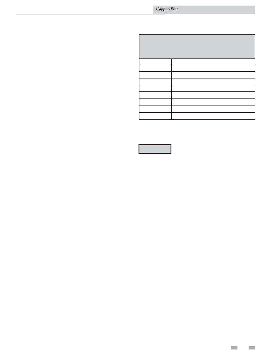
TABLE - 4C
BOILER TEMPERATURE RISE AT MAXIMUM FLOW
Temperature Rise at Full Rate Fire, 55 and 90 GPM
Maximum Flow
Model
Temperature Rise °F
497
15 @ 55 GPM
647
20 @ 55 GPM
747
23 @ 55 GPM
987
19 @ 90 GPM
1257
24 @ 90 GPM
1437
27 @ 90 GPM
1797
34 @ 90 GPM
2067
39 @ 90 GPM