Venting – Lochinvar COPPER-FIN 497 - 2067 User Manual
Page 17
17
2
Venting
(continued)
Barometric damper location
Any venting system option that requires a barometric
damper must adhere to the following directions for optimum
performance. The preferred location for the barometric damper
is in a tee or collar installed in the vertical pipe rising from the
unit’s flue outlet. The barometric damper MUST NOT be
installed in a bull head tee installed on the unit’s flue outlet.
The tee or collar containing the barometric damper should
be approximately three feet vertically above the connection to
the unit’s flue outlet. This location ensures that any positive
velocity pressure from the unit’s internal combustion fan is
dissipated and the flue products are rising due to buoyancy
generated from the temperature of the flue products. Adjust
the weights on the damper to ensure that draft is maintained
within the specified ranges.
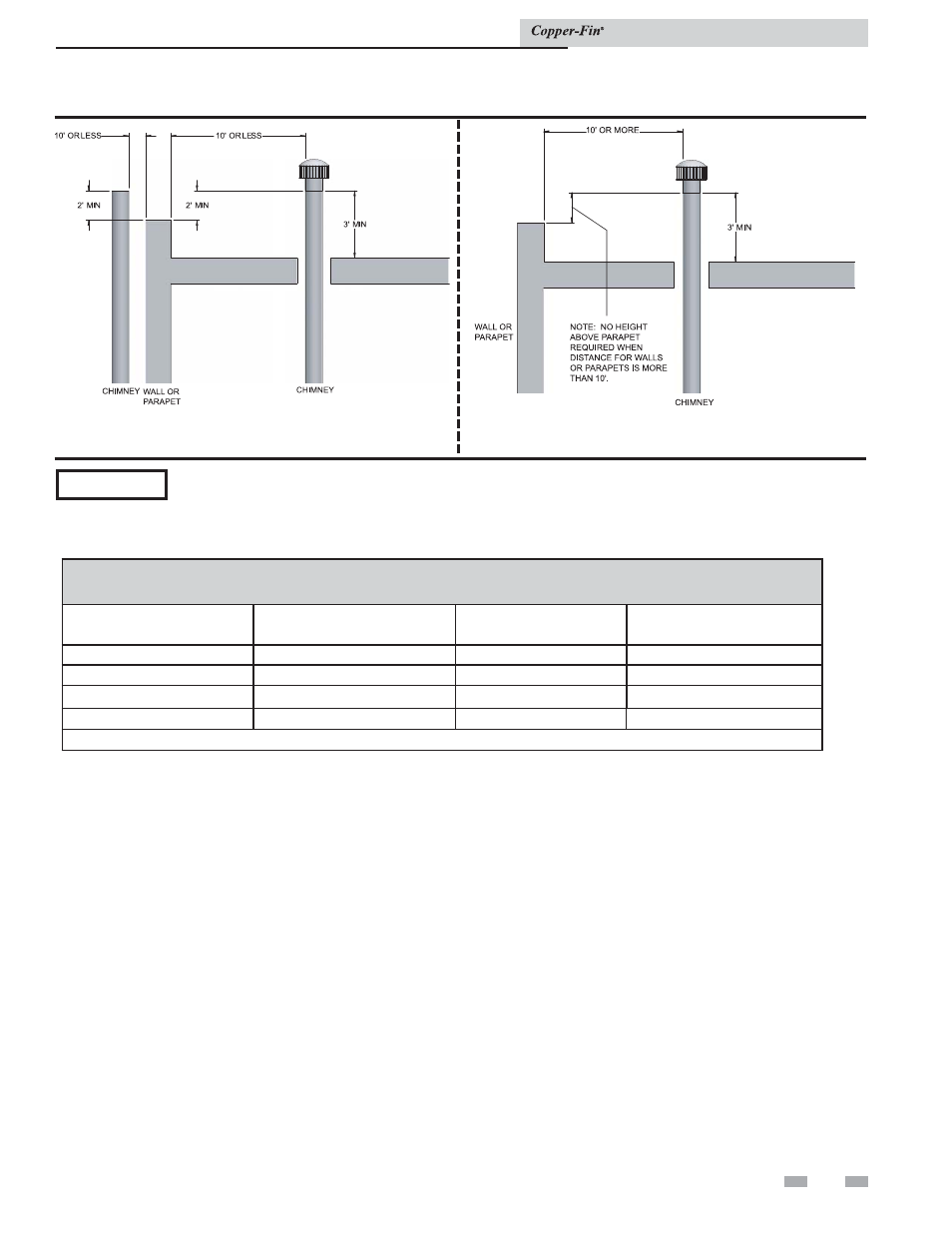
Figure 2-4_Vent termination from flat roof - 10 ft. or more
from parapet wall
Figure 2-3_Vent termination from flat roof - 10 ft. or
less from parapet wall
Vent system options
Vent System Options
This unit has two venting options.
1. Conventional
Negative
Draft
Venting
This option uses a vertical rooftop flue termination.
Combustion air is supplied from the mechanical room.
See page 15 for detailed information.
2. Outdoor
Installation
Venting
This option uses the installation of special air inlet and
vent caps on the unit.
All units are shipped from the factory equipped for
conventional negative draft venting. All other optional vent
systems require the installation of specific vent kits and venting
materials. The following is a detailed explanation of the
installation requirements for each venting system, components
used and part numbers of vent kits for each model.
ƽ CAUTION Units which are shut down or will not operate may experience freezing due to convective air flow in flue
pipe, through the air inlet, or from negative pressure in the equipment room. In cold climates, operate pump
continuously to help prevent freezing of boiler water. Provide proper freeze protection. See Freeze Protection,
page 46.
TABLE 2A
FLUE PIPE SIZES
MODEL
FLUE SIZE
MODEL
FLUE SIZE
497
6''
1257
12''
647
8''
1437
12''
747
8''
1797
14''
987
10''
2067
14''
Installer may increase diameter one pipe size for ease of installation, if needed.
Installation & Service Manual