Removing the main pcb board – SATO CL 408e User Manual
Page 172
Page 9-18
Section 9. Optional Accessories
SATO CL408e/CL412e Service Manual
PN 9001078
Rev. B
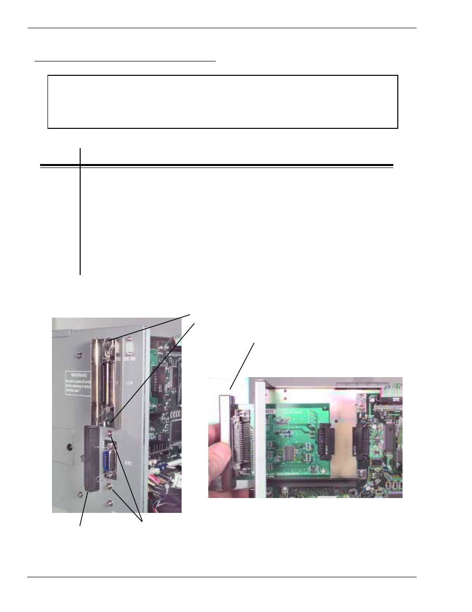
PCMCIA Memory Expansion Installation
STEP
PROCEDURE
4.
If an interface card is installed remove (2) screws holding the card to the
rear cover and pull away to detach the card from the PCB Board.
Figs. 9-32
5.
Remove (2) screws holding EXT Connector to cabinet. Figs. 9-32
6.
Note cable connection locations, then disconnect all cables from the PCB
Board. Fig. 9-33
7.
Remove (3) screws holding the PCB Board to the frame. Fig. 9-34
Remove the board from the printer and set aside for installing the
Memory PCB Board. Continue on Page 9-20.
REMOVE (2) SCREWS AND PULL
AWAY TO DETACH IF INTERFACE
CARD IS INSTALLED
REMOVE (2) SCREWS
HOLDING EXT CONNECTOR
TO CABINET
NOTE: Many of the components on this board are susceptible to damage by static
electricity. To avoid damage from static electricity, do not unpack new circuit boards
from anti-static bags until instructed to do so and use a wrist grounding strap.
PCMCIA
MEMORY CARD
COVER
Removing the Main PCB Board
Figs. 9-32