Schematic diagram, Electrical wiring diagrams, Symbols description – Sanyo CL4232 User Manual
Page 46
– 46 –
SM830078
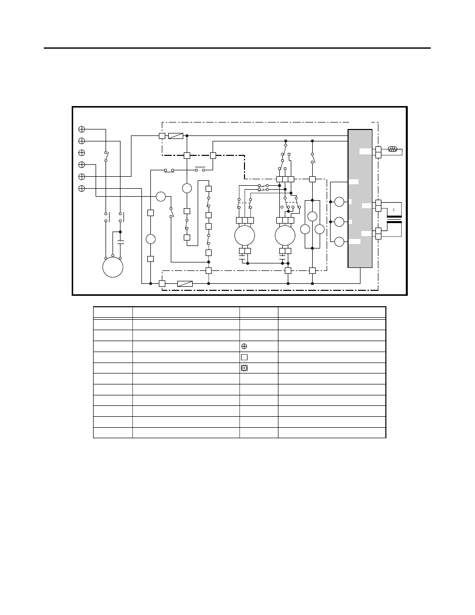
10. ELECTRICAL WIRING DIAGRAMS
(2)
Outdoor Unit
2
2
2
2
2
CL4232
• Schematic Diagram
1
3
2
1
2
1
TR
AC 208V
230V
AC 14V
TH
Outdoor
Temperature
CM
52C
C
R
U
S
V
S
R
RC1
7
5
9
1
6
5
7
FMO2
RC3
RY1
RY3
RY2
4Y
52C
14
13
52C
1Y
41
42
2Y
3Y
H
L
M
1
3
1 2
6
5
7
FMO1
RC2
49FO2
49FO1
63PH
1Y
COM
COM
1 2
F2 (3A)
F1 (3A)
3Y
2Y
1Y
4Y
RY1
RY2
RY3
M
HGBV
L
+12V
PRY
SEC
Temp
3
4
1
1
1
3
2
4
3
3
52C
1
2
3
CH
-1
-2
-G
-4
-L1
-L2
Terminal
Plate (6P)
CR-CL2432
Controller
S
854-2-5268-897-00-0 (CL4232)
Symbols
Description
CM
CH
FMO1, 2
49FO1, 2
52C
TR
TH
RC1, 2, 3
RY1, 2, 3
1Y~4Y
CR-CL2432
Compressor Motor
Crankcase Heater
Outdoor Fan Motor
Outdoor Fan Motor Thermal Protector
Compressor Motor Magnetic Contactor
Power Transformer
Thermistor (Outdoor Temperature)
Running Capacitor
Auxiliary Relay
Auxiliary Relay
Outdoor Controller
Symbols
Description
F1, 2
63PH
Fuse
High Pressure Switch
Terminal Plate
Connector
Terminal