Schematic diagram, Electrical wiring diagrams – Sanyo CL4232 User Manual
Page 44
– 44 –
SM830078
10. ELECTRICAL WIRING DIAGRAMS
(2)
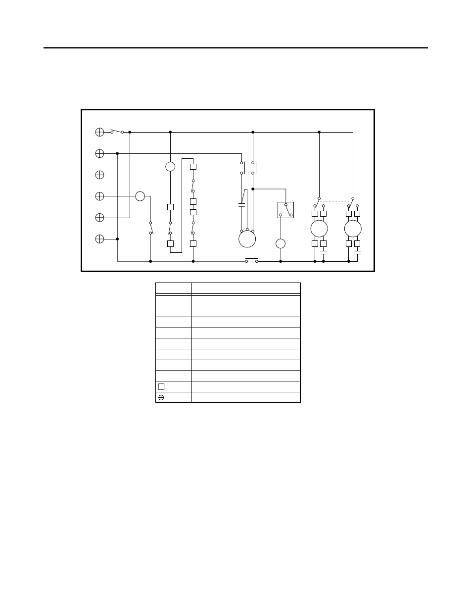
Outdoor Unit
1
1
1
1
1
C4232
S
V
R
U
C
L
RC1
S
C
R
52C
H
23S
1Y
CM
RC2
FMO1
3
1
5
1Y
6
5
2
1
RC3
FMO2
4
2
6
6
5
2
1
3
4
3
49FO1
Terminal Plate (6P)
49FO2
63PH
2Y
4
1
2Y
2
2Y
52C
T
W
52C
-1
-L2
-L1
-4
-G
-2
• Schematic Diagram
S
854-2-5268-896-00-0 (C4232)
Symbols
Description
CM
FMO1, 2
49FO1, 2
52C
63PH
23S
RC1, 2, 3
1Y, 2Y
Compressor Motor
Outdoor Fan Motor
Outdoor Fan Motor Thermal Protector
Compressor Motor Magnetic Contactor
High Pressure Switch
Fan Speedcontrol Thermostat
Running Capacitor
Auxiliary Relay
Connector
Terminal Plate
This manual is related to the following products:
See also other documents in the category Sanyo Conditioners:
- ECO-i WCHDZ20053 (2 pages)
- CL0951 (3 pages)
- ECO G SPW-GU075XH (9 pages)
- CM1972 (99 pages)
- CR365GX56 (1 page)
- 42XS32A (3 pages)
- CL2432A (3 pages)
- 9 (2 pages)
- KH3072R / C3072R (180 pages)
- CH0971 (2 pages)
- 26UW72R (2 pages)
- C2432 (17 pages)
- CR1304GDZH8 (1 page)
- KH2672R (48 pages)
- ECOi C0905DXHN8 (10 pages)
- CH1251 (98 pages)
- 30KS32A (3 pages)
- Concealed Duct & Heat Pump H 13.9-14.9 SEER (2 pages)
- 42TLS32A (3 pages)
- CL2462R (58 pages)
- C1251 (83 pages)
- DHX3652 (114 pages)
- 42XHW72R (2 pages)
- 09KS71 (2 pages)
- C3632A (3 pages)
- 18KS72 (2 pages)
- 12XS71 (2 pages)
- ECO R410A (48 pages)
- KS2472 (117 pages)
- INVERTER SPLIT SYSTEM 8.53E+13 (24 pages)
- C3082 (104 pages)
- KHHS2672R (4 pages)
- CHX06052 (246 pages)
- CL1211 (16 pages)
- CH3082 (109 pages)
- Indoor Unit thx1852 (4 pages)
- 42TW72R (2 pages)
- KHS1872 (111 pages)
- CHDZ14053 (265 pages)
- CL0971 (4 pages)
- CHDX14053 (243 pages)
- 09KS51 (3 pages)
- 12RLS11 (3 pages)
- CL1852 (81 pages)