Schematic diagram, Electrical wiring diagrams, Symbols description – Sanyo CL4232 User Manual
Page 42
– 42 –
SM830078
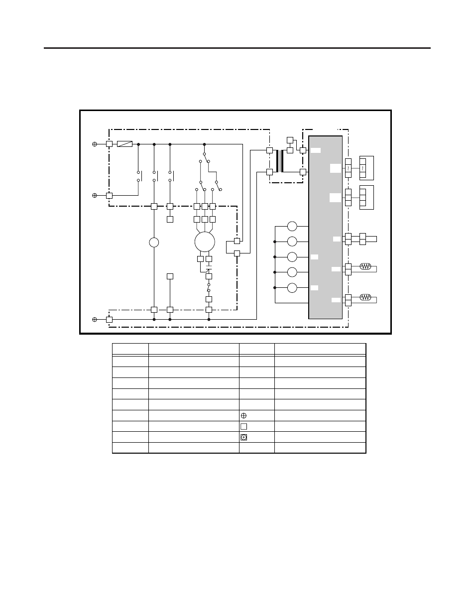
10. ELECTRICAL WIRING DIAGRAMS
(1)
Indoor Unit
2
2
2
2
2
TS4232
• Schematic Diagram
S
854-2-5268-593-00-0 (TS3632)
2
1
3
1
3
1
2
IND
3
1
2
7
1
7
1
SW
TR1
PRY
Coil
TH1
2
1
Room
TH2
CR-TS2432
Controller
1
1
3
5
F1
(3A)
1
2
1
3
2
RY2
RY1
RY3
RY4
RY5
3
LM
1
RY5
4P-4
4P-2
4P-1
1
FMI
1
2
1
9
8
7
3
5
4
5
6
RY1
RY2
RY2
H
DP
L
M
1
3
49FMI
RY3
RY4
Symbols
Description
FMI
49FI
RC1
F1
DP
LM
TR1
RY1~RY5
FS
Indoor Fan Motor
Indoor Motor Thermal Protector
Running Capacitor
Fuse
Drain Pump
Auto Louver Motor
Power Transformer
Auxiliary Relay
Float Switch
Symbols
Description
TH1
TH2
CR-TS2432
IND
SW
Thermistor (Indoor Coil)
Room Thermistor
Indoor Controller
Indicator Lamp Assy
Switch Assy
Terminal Plate
Connector
Terminal
SEC
LM
TH1
TH2
DP
49FI
RC1
1
2
2
FS
W/
LESS
SW
ASSY
2
1
This manual is related to the following products: