Table 16.2. usb0 controller registers – Silicon Laboratories C8051F347 User Manual
Page 165
Rev. 1.3
165
C8051F340/1/2/3/4/5/6/7/8/9/A/B/C/D
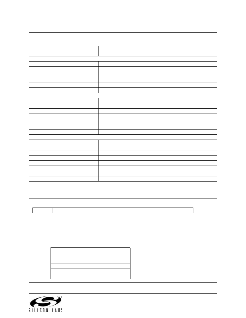
USB Register Definition 16.4. INDEX: USB0 Endpoint Index
Table 16.2. USB0 Controller Registers
USB Register
Name
USB Register
Address
Description
Page Number
Interrupt Registers
IN1INT
0x02
Endpoint0 and Endpoints1-3 IN Interrupt Flags
OUT1INT
0x04
Endpoints1-3 OUT Interrupt Flags
CMINT
0x06
Common USB Interrupt Flags
IN1IE
0x07
Endpoint0 and Endpoints1-3 IN Interrupt Enables
OUT1IE
0x09
Endpoints1-3 OUT Interrupt Enables
CMIE
0x0B
Common USB Interrupt Enables
Common Registers
FADDR
0x00
Function Address
POWER
0x01
Power Management
FRAMEL
0x0C
Frame Number Low Byte
FRAMEH
0x0D
Frame Number High Byte
INDEX
0x0E
Endpoint Index Selection
CLKREC
0x0F
Clock Recovery Control
FIFOn
0x20–0x23
Endpoints0-3 FIFOs
Indexed Registers
E0CSR
0x11
Endpoint0 Control / Status
EINCSRL
Endpoint IN Control / Status Low Byte
EINCSRH
0x12
Endpoint IN Control / Status High Byte
EOUTCSRL
0x14
Endpoint OUT Control / Status Low Byte
EOUTCSRH
0x15
Endpoint OUT Control / Status High Byte
E0CNT
0x16
Number of Received Bytes in Endpoint0 FIFO
EOUTCNTL
Endpoint OUT Packet Count Low Byte
EOUTCNTH
0x17
Endpoint OUT Packet Count High Byte
Bits7–4: Unused. Read = 0000b; Write = don’t care.
Bits3–0: EPSEL: Endpoint Select
These bits select which endpoint is targeted when indexed USB0 registers are accessed.
R
R
R
R
R/W
R/W
R/W
R/W
Reset Value
-
-
-
-
EPSEL
00000000
Bit7
Bit6
Bit5
Bit4
Bit3
Bit2
Bit1
Bit0
USB Address:
0x0E
INDEX
Target Endpoint
0x0
0
0x1
1
0x2
2
0x3
3
0x4–0xF
Reserved