Sfr definition 14.6. clksel: clock select – Silicon Laboratories C8051F347 User Manual
Page 140
C8051F340/1/2/3/4/5/6/7/8/9/A/B/C/D
140
Rev. 1.3
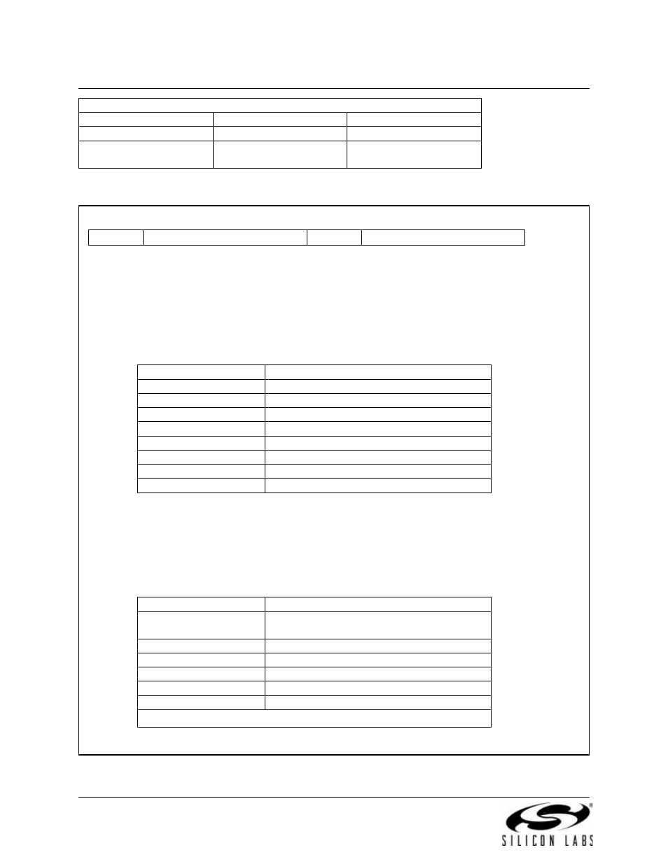
SFR Definition 14.6. CLKSEL: Clock Select
USB Clock
External Oscillator / 4
USBCLK = 101b
External Oscillator
Crystal Oscillator Mode
24 MHz Crystal
XOSCMD = 110b
XFCN = 111b
Internal Oscillator
Clock Signal
Input Source Selection
Register Bit Settings
Bit 7:
Unused. Read = 0b; Write = don’t care.
Bits6–4: USBCLK2–0: USB Clock Select
These bits select the clock supplied to USB0. When operating USB0 in full-speed mode, the
selected clock should be 48 MHz. When operating USB0 in low-speed mode, the selected
clock should be 6 MHz.
Bit3:
Unused. Read = 0b; Write = don’t care.
Bits2–0: CLKSL2–0: System Clock Select
These bits select the system clock source. When operating from a system clock of 25 MHz
or less, the FLRT bit should be set to ‘0’. When operating with a system clock of greater than
25 MHz (up to 48 MHz), the FLRT bit (FLSCL.4) should be set to ‘1’. See
“10. Prefetch Engine” on page 99
R/W
R/W
R/W
R/W
R/W
R/W
R/W
R/W
Reset Value
-
USBCLK
-
CLKSL
00000000
Bit7
Bit6
Bit5
Bit4
Bit3
Bit2
Bit1
Bit0
SFR Address
0xA9
USBCLK
Selected Clock
000
4x Clock Multiplier
001
Internal Oscillator / 2
010
External Oscillator
011
External Oscillator / 2
100
External Oscillator / 3
101
External Oscillator / 4
110
RESERVED
111
RESERVED
CLKSL
Selected Clock
000
Internal Oscillator (as determined by the
IFCN bits in register OSCICN)
001
External Oscillator
010
4x Clock Multiplier / 2
011*
4x Clock Multiplier*
100
Low-Frequency Oscillator
101-111
RESERVED
*Note: This option is only available on 48 MHz devices.