Figure 21.7. timer 2 capture mode (t2split = ‘1’) – Silicon Laboratories C8051F347 User Manual
Page 246
C8051F340/1/2/3/4/5/6/7/8/9/A/B/C/D
246
Rev. 1.3
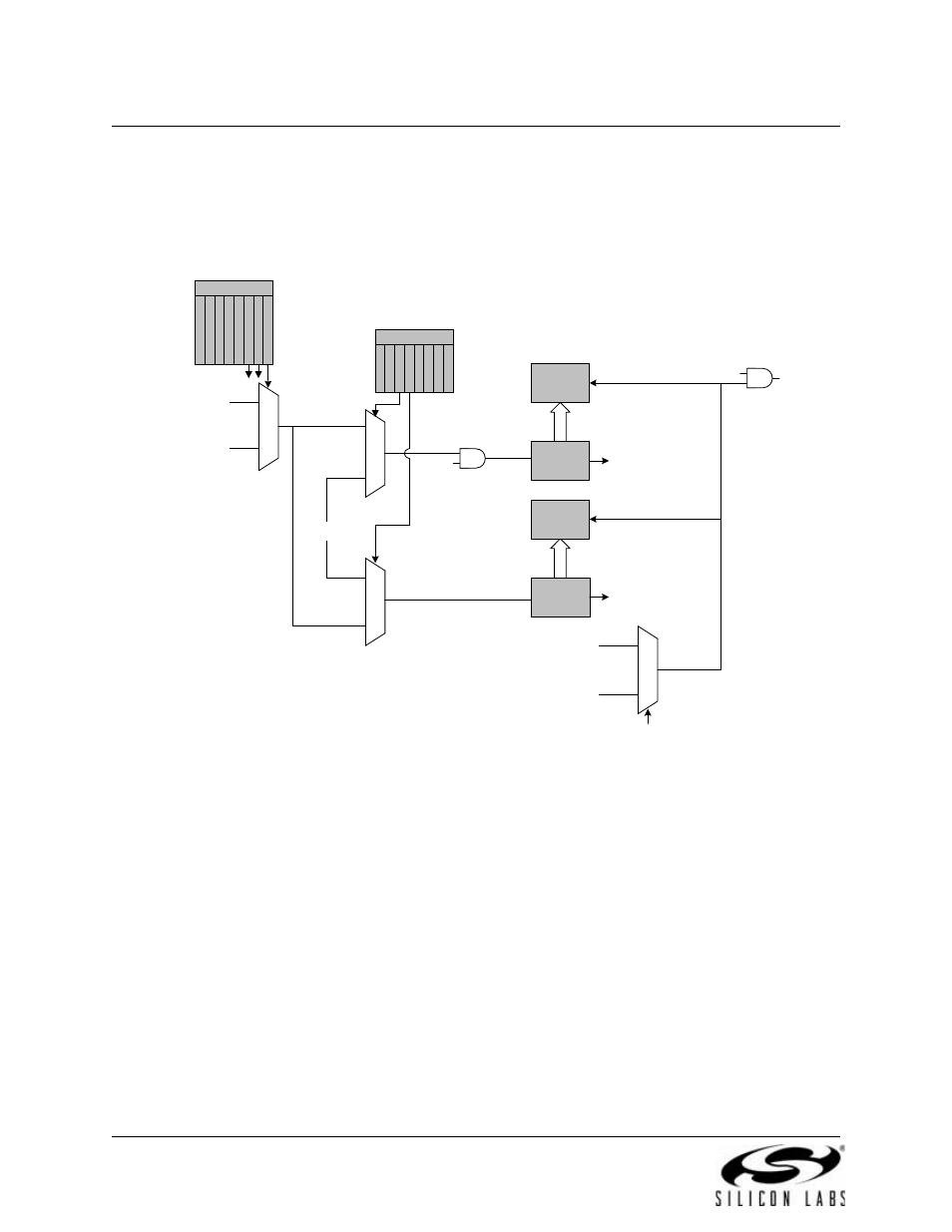
When T2SPLIT = ‘1’, the Timer 2 registers (TMR2H and TMR2L) act as two 8-bit counters. Each counter
counts up independently and overflows from 0xFF to 0x00. Each time a capture event is received, the con-
tents of the Timer 2 registers are latched into the Timer 2 Reload registers (TMR2RLH and TMR2RLL). A
Timer 2 interrupt is generated if enabled.
Figure 21.7. Timer 2 Capture Mode (T2SPLIT = ‘1’)
SYSCLK
TCLK
0
1
TR2
External Clock / 8
SYSCLK / 12
0
1
1
0
TMR2H
TMR2RLH
TCLK
TMR2L
TMR2RLL
To ADC,
SMBus
To SMBus
CKCON
T
3
M
H
T
3
M
L
S
C
A
0
S
C
A
1
T
0
M
T
2
M
H
T
2
M
L
T
1
M
TMR2CN
T
F
2
H
T
F
2
L
T
2
X
C
L
K
T
2
C
S
S
T
R
2
T
F
2
L
E
N
T
2
C
E
T
2
S
P
L
I
T
Capture
Enable
Capture
Interrupt
USB Start-of-Frame (SOF)
Low-Frequency Oscillator
Falling Edge
0
1
T2CSS