Endpoint addressing, Table 16.1. endpoint addressing scheme, Usb transceiver – Silicon Laboratories C8051F347 User Manual
Page 160: Endpoint addressing 16.2.usb transceiver
C8051F340/1/2/3/4/5/6/7/8/9/A/B/C/D
160
Rev. 1.3
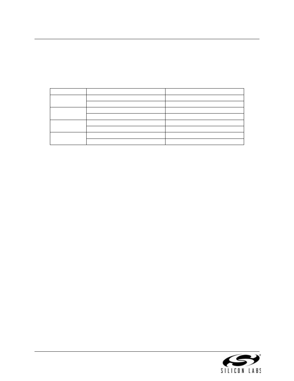
16.1. Endpoint Addressing
A total of eight endpoint pipes are available. The control endpoint (Endpoint0) always functions as a
bi-directional IN/OUT endpoint. The other endpoints are implemented as three pairs of IN/OUT endpoint
pipes:
16.2. USB Transceiver
The USB Transceiver is configured via the USB0XCN register shown in SFR Definition 16.1. This configu-
ration includes Transceiver enable/disable, pull-up resistor enable/disable, and device speed selection
(Full or Low Speed). When bit SPEED = ‘1’, USB0 operates as a Full Speed USB function, and the on-chip
pull-up resistor (if enabled) appears on the D+ pin. When bit SPEED = ‘0’, USB0 operates as a Low Speed
USB function, and the on-chip pull-up resistor (if enabled) appears on the D- pin. Bits4-0 of register
USB0XCN can be used for Transceiver testing as described in SFR Definition 16.1. The pull-up resistor is
enabled only when VBUS is present (see
Section “8.2. VBUS Detection” on page 69
for details on
VBUS detection).
Important Note: The USB clock should be active before the Transceiver is enabled.
Table 16.1. Endpoint Addressing Scheme
Endpoint
Associated Pipes
USB Protocol Address
Endpoint0
Endpoint0 IN
0x00
Endpoint0 OUT
0x00
Endpoint1
Endpoint1 IN
0x81
Endpoint1 OUT
0x01
Endpoint2
Endpoint2 IN
0x82
Endpoint2 OUT
0x02
Endpoint3
Endpoint3 IN
0x83
Endpoint3 OUT
0x03