Memory organization, Figure 9.2. on-chip memory map for 64 kb devices – Silicon Laboratories C8051F347 User Manual
Page 79
Rev. 1.3
79
C8051F340/1/2/3/4/5/6/7/8/9/A/B/C/D
9.2.
Memory Organization
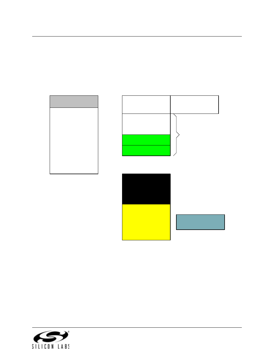
The memory organization of the CIP-51 System Controller is similar to that of a standard 8051. There are
two separate memory spaces: program memory and data memory. Program and data memory share the
same address space but are accessed via different instruction types. The CIP-51 memory organization is
shown in Figure 9.2 and Figure 9.3.
Figure 9.2. On-Chip Memory Map for 64 kB Devices
PROGRAM/DATA MEMORY
(FLASH)
(Direct and Indirect
Addressing)
0x00
0x7F
Upper 128 RAM
(Indirect Addressing
Only)
0x80
0xFF
Special Function
Register's
(Direct Addressing Only)
DATA MEMORY (RAM)
General Purpose
Registers
0x1F
0x20
0x2F
Bit Addressable
Lower 128 RAM
(Direct and Indirect
Addressing)
0x30
INTERNAL DATA ADDRESS SPACE
EXTERNAL DATA ADDRESS SPACE
XRAM - 4096 Bytes
(Accessable using MOVX
instruction)
0x0000
0x0FFF
Off-Chip XRAM
(Available only on devices
with EMIF)
0x0400
0xFFFF
FLASH
(In-System
Programmable in 512
Byte Sectors)
0x0000
RESERVED
0xFC00
0xFBFF
USB FIFOs
1024 Bytes
0x07FF
0x1000
0xFFFF