Back panel, Power adapter, Radio transceivers – Juniper Networks SSG 20 User Manual
Page 16: Power adapter radio transceivers, Grounding lug, Antennae types, Usb port
SSG 20 Hardware Installation and Configuration Guide
16
Back Panel
Back Panel
This section describes the following elements on the back panel of an SSG 20
device:
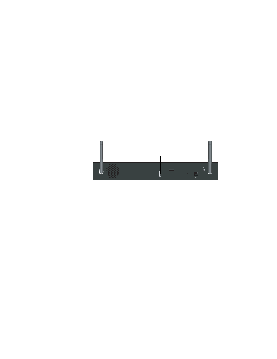
Figure 6: Back Panel of an SSG 20-WLAN Device
Power Adapter
The POWER LED on the front panel of a device either glows green or is off. Green
indicates correct function, and off indicates power-adapter failure or that the device
is off.
Radio Transceivers
The SSG 20-WLAN contains two wireless connectivity radio transceivers, which
support 802.11a/b/g standards. The first transceiver (WLAN 0) uses the 2.4 GHz
radio band, which supports the 802.11b standard at 11 Mbps, the 802.11g standard
at 54 Mbps, and 802.11 SuperG standard at 108 Mbps. The second radio transceiver
(WLAN 1) uses the 5GHz radio band, which supports the 802.11a standard at 54
Mbps. For information on configuring the wireless radio band, see “This section
provides information for configuring the wireless interface on the SSG 20-WLAN
device. Wireless networks consist of names referred to as Service Set Identifiers
(SSIDs). Specifying SSIDs allows you to have multiple wireless networks reside in
the same location without interfering with each other. An SSID name can have a
maximum of 32 characters. If a space is part of the SSID name string, then the
string must be enclosed with quotation marks. Once the SSID name is set, more
SSID attributes can be configured.To use the wireless local area network (WLAN)
capabilities on the device, you must configure at least one SSID and bind it to a
wireless interface.” on page 37.
B
A
L OCK
DC POWER
1 2 V
A
4
RESET
USB
Power
adapter
USB port
Grounding
lug
Antenna B
Antenna A
Reset
pinhole
Device
security lock