IBM 12.1(22)EA6 User Manual
Page 282
14-4
Cisco Systems Intelligent Gigabit Ethernet Switch Modules for the IBM BladeCenter, Software Configuration Guide
24R9746
Chapter 14 Configuring IGMP Snooping and MVR
Understanding IGMP Snooping
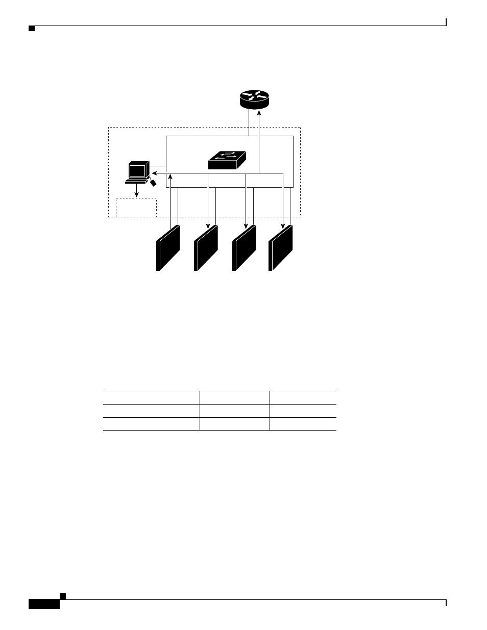
Figure 14-1
Initial IGMP Join Message
Router A sends a general query to the switch, which forwards the query to ports 2 through 5, all members
of the same VLAN. Host 1 wants to join multicast group 224.1.2.3 and multicasts an IGMP membership
report (IGMP join message) to the group with the equivalent MAC destination address of
0x0100.5E01.0203. When the CPU receives the IGMP report multicast by Host 1, the CPU uses the
information in the IGMP report to set up a forwarding-table entry, as shown in
, that includes
the port numbers of Host 1, the router, and the switch internal CPU.
Note that the switch hardware can distinguish IGMP information packets from other packets for the
multicast group.
•
The first entry in the table tells the switching engine to send IGMP packets to only the switch CPU.
This prevents the CPU from becoming overloaded with multicast frames.
•
The second entry tells the switching engine to send frames addressed to the 0x0100.5E01.0203
multicast MAC address that are not IGMP packets (!IGMP) to the router and to the host that has
joined the group.
If another host (for example, Host 4) sends an unsolicited IGMP join message for the same group
(
), the CPU receives that message and adds the port number of Host 4 to the forwarding table
as shown in
. Note that because the forwarding table directs IGMP messages only to the CPU,
Forwarding
table
CPU
Server
Blade 1
Server
Blade 2
Server
Blade 3
Server
Blade 4
Router A
IGMP report 224.1.2.3
IGESM
Switching engine
1
0
2
3
4
5
92421
Table 14-1
IGMP Snooping Forwarding Table
Destination Address
Type of Packet
Ports
0100.5exx.xxxx
IGMP
0
0100.5e01.0203
!IGMP
1, 2