Figure 11-6 – IBM 12.1(22)EA6 User Manual
Page 219
11-7
Cisco Systems Intelligent Gigabit Ethernet Switch Modules for the IBM BladeCenter, Software Configuration Guide
24R9746
Chapter 11 Configuring Optional Spanning-Tree Features
Understanding Optional Spanning-Tree Features
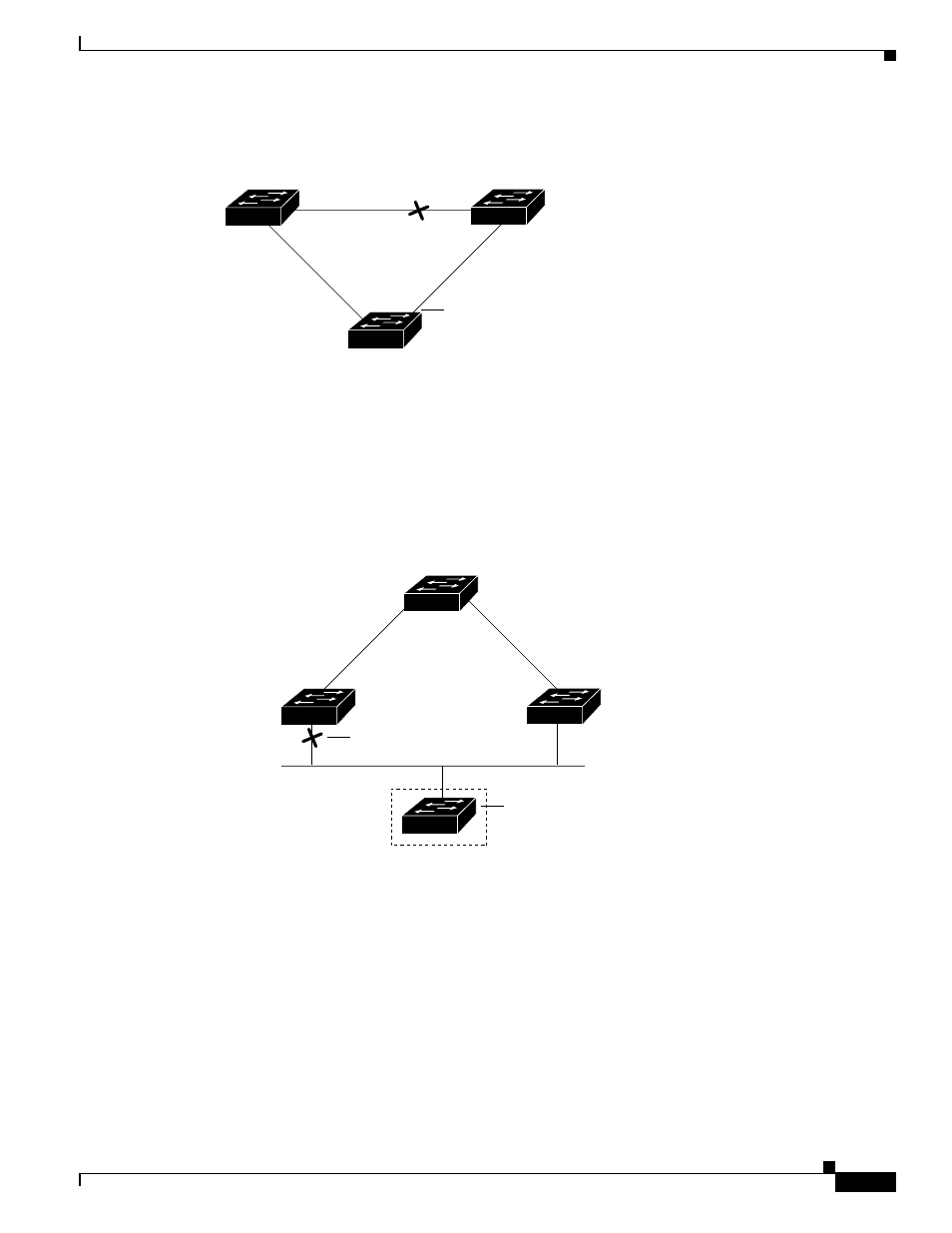
Figure 11-6
BackboneFast Example After Indirect Link Failure
If a new switch is introduced into a shared-medium topology as shown in
, BackboneFast is
not activated because the inferior BPDUs did not come from the recognized designated bridge
(Switch B). The new switch begins sending inferior BPDUs that indicate it is the root switch. However,
the other switches ignore these inferior BPDUs, and the new switch learns that Switch B is the
designated bridge to Switch A, the root switch.
Figure 11-7
Adding a Switch in a Shared-Medium Topology
L1
L2
L3
Switch C
Switch A
(Root)
Switch B
Link failure
44964
BackboneFast changes port
through listening and learning
states to forwarding state.
Switch A
(Root)
Switch C
Switch B
(Designated bridge)
Added switch
44965
Blocked port