9 isa signals, 10 isa and x-bus signals, 9 isa signals 3.10 isa and x-bus signals – Intel 440GX User Manual
Page 83
Intel
®
440GX AGPset Design Guide
3-23
Design Checklist
Third, if the design currently uses an in-line active gate/buffer on PCIRST# to drive the PCI bus,
consider removal of this gate/buffer entirely. The PIIX4/PIIX4E is designed to drive the entire PCI
bus.
3.9
ISA Signals
3.10
ISA and X-Bus Signals
•
The PIIX4E will support a maximum of 5 ISA slots.
•
XOE# and XDIR# are connected to the ULTRA I/O device.
•
If internal RTC is used, RTCALE and RTCCS# are no connect or become general purpose
outputs by programming the General Configuration Register(GENCFG) in the Function 0,
offset B0h–B3h.
•
The LM79 is connected to the X-Bus due to the functionality of the PGCS[1:0]# pins on the
PIIX4E.
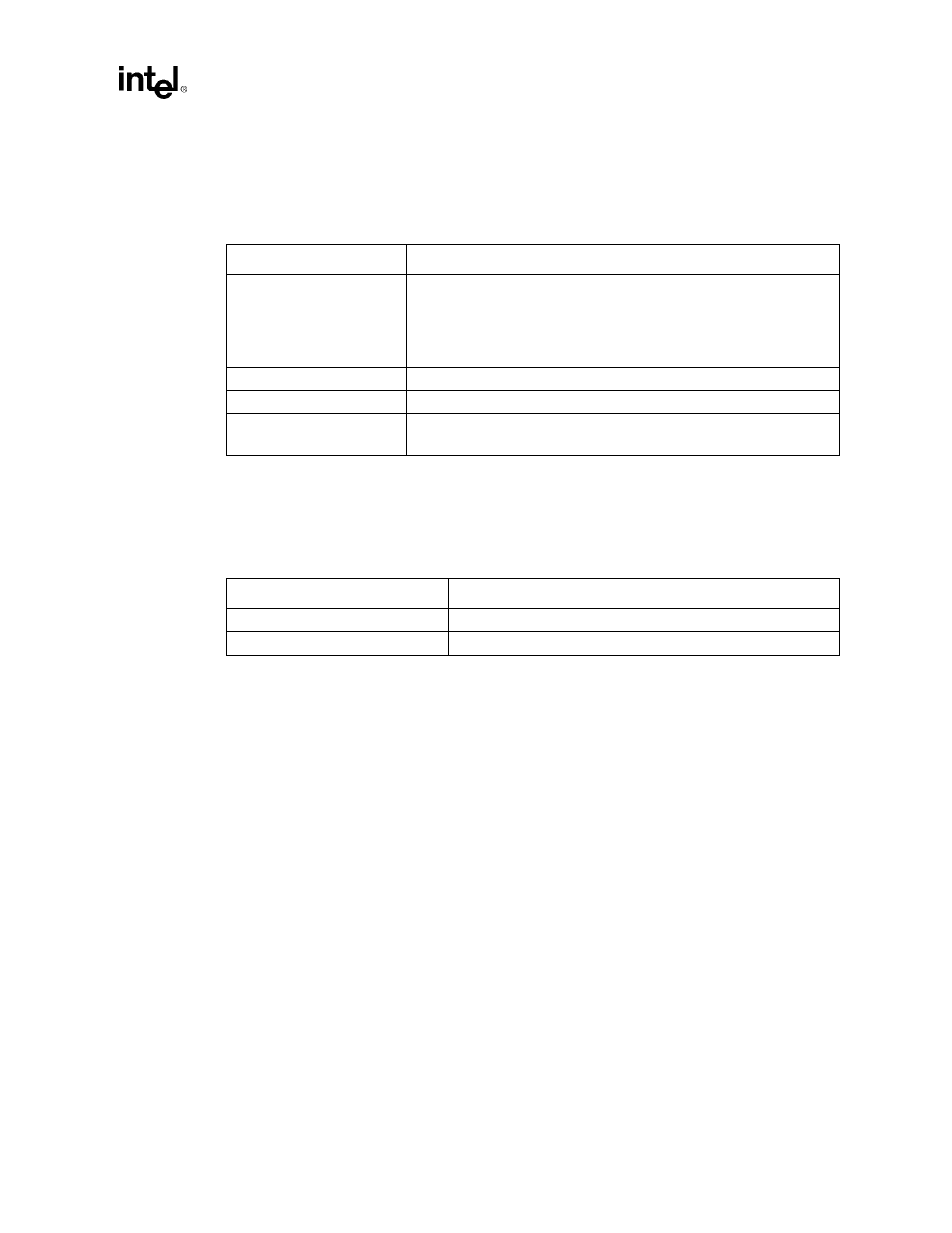
Table 3-10. Non-PIIX4E PCI Signals
SIGNAL
CONNECTION
ACK64#,
PERR#,
PLOCK#,
REQ64#
(5V PCI environment) 2.7K ohm pull-up resistors to 5V.
(3V PCI environment) 10K ohm pull-up resistors to 3.3V.
PERR# and PLOCK# can be connected together across PCI slots and pulled
up by single resistor.
Each REQ64# and ACK64# requires its own pull-up.
GNT[3:0]#
Connected between PCI slots and 82443GX. 8.2K ohm pull-up to VCC3.
IDSEL lines to PCI connectors
100 ohm series resistor recommended per the PCI spec.
SBO#,
SDONE
5.6K ohm pull-up to VCC.
Table 3-11. Non-PIIX4E ISA Signals
SIGNAL
CONNECTION
OSC1
Connected to CK100 through 22 ohm resistor.
RMASTER#
1K ohm pull-up to VCC.