Intel 440GX User Manual
Page 45
Intel
®
440GX AGPset Design Guide
2-21
Motherboard Layout and Routing Guidelines
For trace lengths that are between 1.0 inch and 4.5 inches, a 1:1 trace spacing is recommended for
data lines. The strobe requires a 1:2 trace spacing. This is for designs that require less than 4.5
inches between the AGP device and the AGP target.
Longer lines have more crosstalk. Therefore, to maintain skew, longer line lengths require a greater
amount of spacing between traces. For line lengths greater than 4.5” and less than 12.0”, 1:2
routing is recommended for all data lines and the strobes. For all designs, the line length mismatch
must be less than 0.5” and the strobe must be the longest signal of the group.
In all cases it is best to reduce the line length mismatch wherever possible to insure added margin.
It is also best to separate the traces by as much as possible to reduce the amount of trace to trace
coupling.
The clock lines on the motherboard can couple with other traces. It is recommended that the clock
spacing (air gap) be at least two times the trace width to any other traces. It is also strongly
recommended that the clock spacing be at least four times the trace width to any strobes.
The clock lines on the motherboard need to be simulated to determine the their proper line length.
The motherboard needs to be designed to the type of clock driver that is being used and
motherboard trace topology. These clocks need to meet the loading of the receiving device as well
as the add-in trace length.
Additionally, control signals less than 8.5 inches can be routed 1:1, while control signals greater
than 8.5 inches should be routed 1:2.
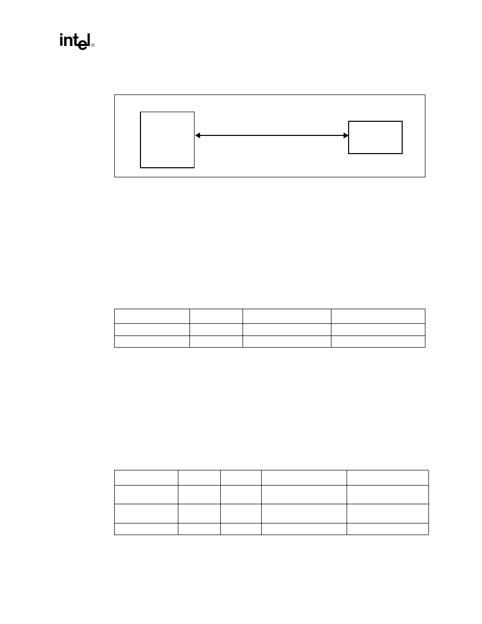
Figure 2-15. On-board AGP Compliant Device Layout Guidelines
AGP
Compliant
Graphics
Device
82443GX
Always 1:2 Strobe Routing
1.0” - 4.5” 1:1 (Data) Routing
1” - 12” 1:2 (Data) Routing
Table 2-15. Source Synchronous Motherboard Recommendations
Width:Space
Trace
Line Length
Line Length Matching
1:1(Data) / 1:2 (Strobe)
Data / Strobe
1.0 in < line length < 4.5 in
-0.5 in, strobe longest trace
1:2
Data / Strobe
1.0 in < line length < 12.0 in
-0.5 in, strobe longest trace
Table 2-16. Control Signal Line Length Recommendations
Width:Space
Board
Trace
Line Length
Pull-up Stub Length
1:1
Motherboard
Control
signals
1.0 in < line length < 8.5 in
< 0.5 in (Strobes < 0.1in)
1:2
Motherboard
Control
signals
1.0 in < line length < 12.5 in
< 0.5 in (Strobes < 0.1in)
1:2 (1:4 to Strobe)
Motherboard
Clock