4 dual processor systems, 1 set network topology and conditions – Intel 440GX User Manual
Page 32
Motherboard Layout and Routing Guidelines
2-8
Intel
®
440GX AGPset Design Guide
2.3.4
Dual Processor Systems
2.3.4.1
Dual Processor Network Topology and Conditions
2.3.4.2
Dual Processor Recommended Trace Lengths
The recommended trace lengths for dual processor designs are summarized in
Table 2-2
. Intel’s
simulations have shown that it is desirable to control the amount of imbalance in the network to
meet ringback specifications at the Intel
®
Pentium
®
II processor when the Intel
®
440GX AGPset
drives. This control is reflected in the recommendations of
Table 2-2
.
NOTES:
1. L4 & L5 are interchangeable
2. It is possible to find working solutions outside the recommendations of
Table 2-2
, as the solution space plot
show. Intel strongly recommends that any traces that fall outside the recommended lengths be simulated to
ensure they meeting timing and signal quality specs.
2.3.5
Single Processor Systems—Single-End Termination (SET)
2.3.5.1
Set Network Topology and Conditions
Removal of the termination resistors from the system board can reduce system cost, at the expense
of increased ringing and reduced solution space. Intel has simulated this topology, known as single
end termination (SET), and found that it can work. However, the topology has some limitations
which are discussed below.
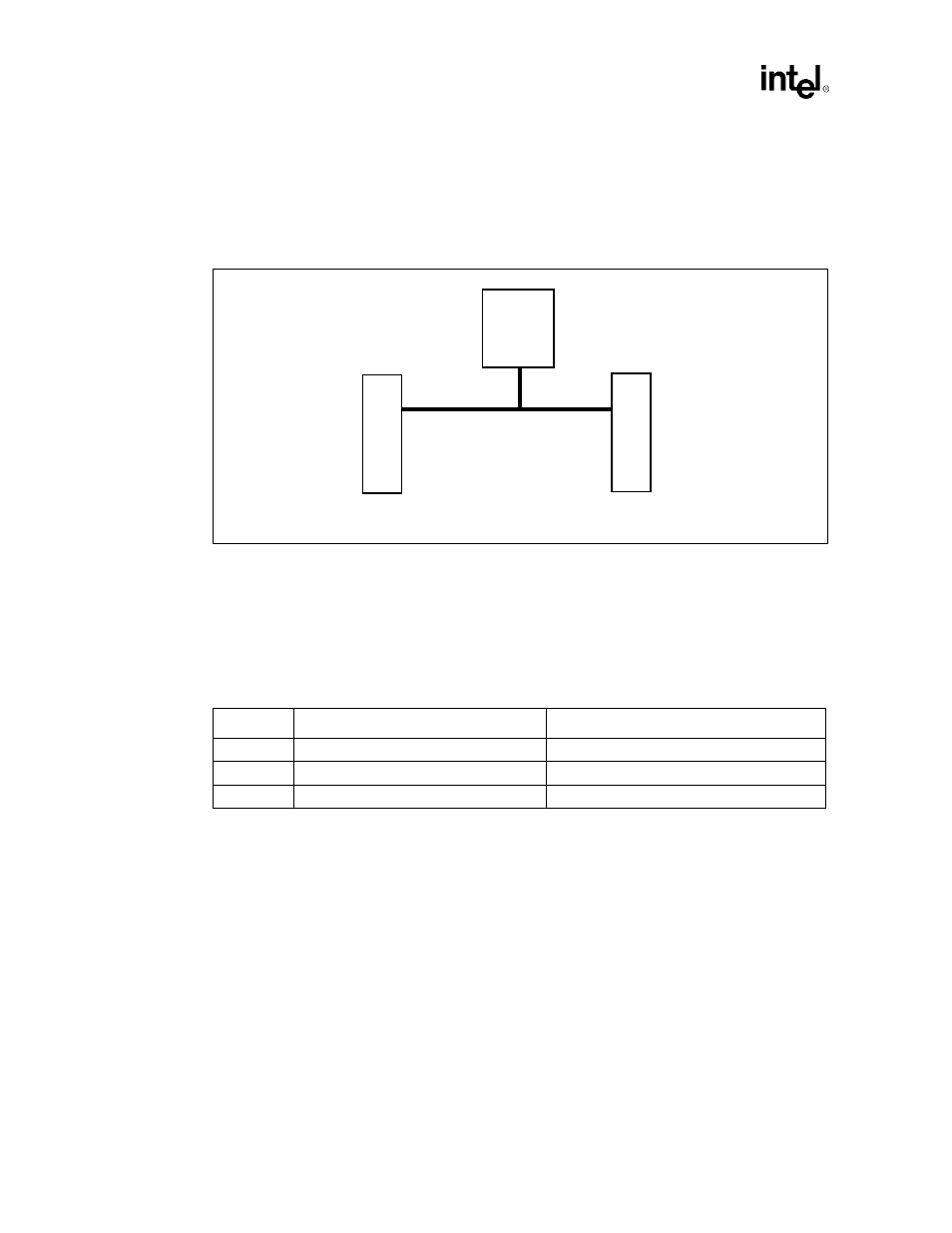
Figure 2-9. Recommended Topology for Dual Processor Design
Sl
ot
1
Intel
®
440GX
AGPset
L5
L4
Sl
ot 1
L3
Table 2-2. Recommended Trace Lengths for Dual Processor Designs
2
Trace
Minimum Length
Maximum Length
L3
0.50”
1.50”
L4
1
1.50”
4.00”
L5
2
L4 - 1.00”, but L4+L5 must be at least 4.00”
L4 + 1.00”, but not greater than 5.00”