Intel 440GX User Manual
Page 26
Motherboard Layout and Routing Guidelines
2-2
Intel
®
440GX AGPset Design Guide
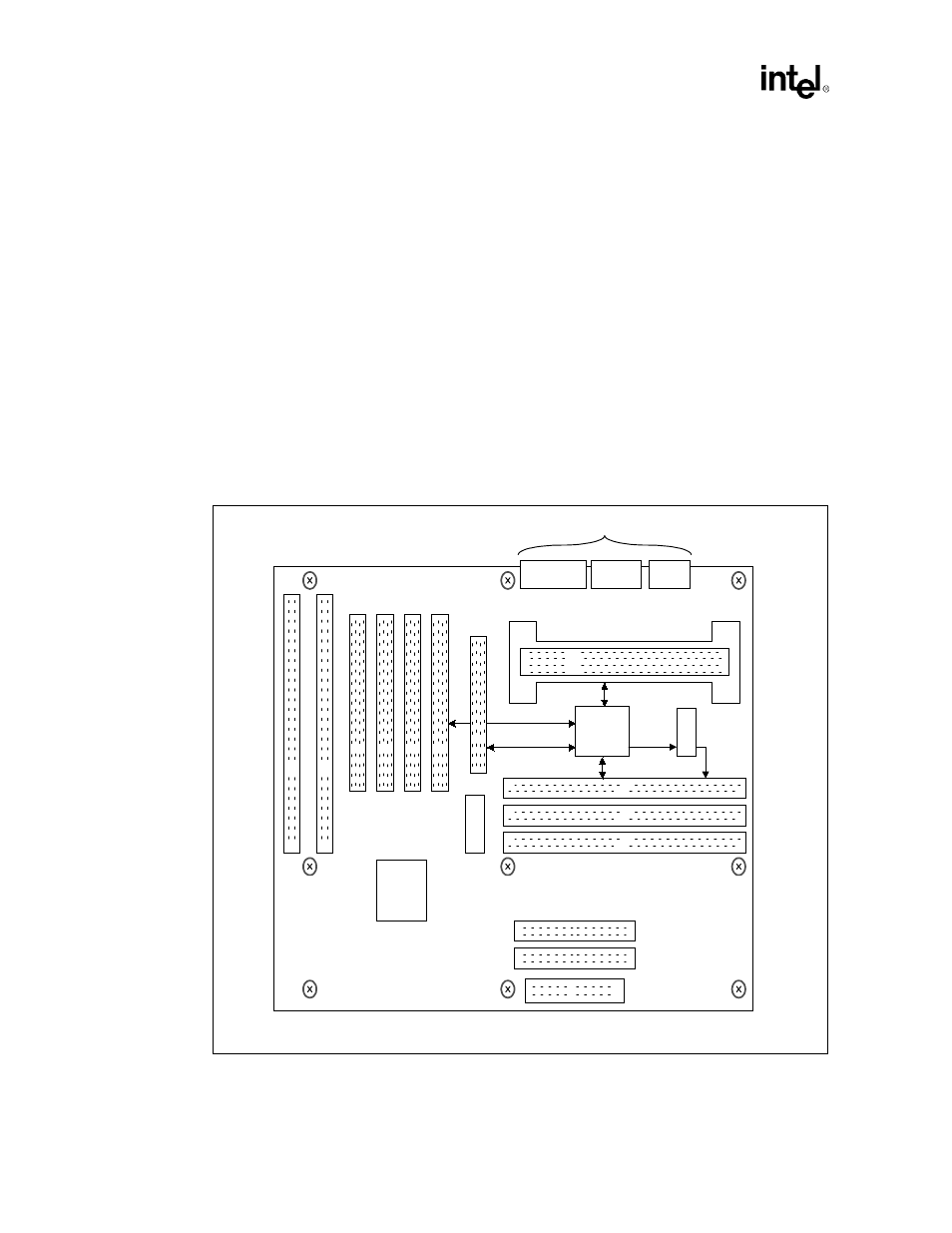
Figure 2-2
and
Figure 2-3
show the proposed component placement for a single processor for both
ATX and NLX form factor designs.
ATX Form Factor:
1. The ATX placement and layout below is recommended for single (UP) Intel
®
Pentium
®
II
processor / Intel
®
440GX AGPset system design.
2. The example placement below shows 4 PCI slots, 2 ISA slots, 4 DIMM sockets, and one AGP
connector.
3. For an ATX form factor design, the AGP compliant graphics device can be either on the
motherboard (device down option), or on an AGP connector (up option).
4. The trace length limitation between critical connections will be addressed later in this
document.
5. The figure below is for reference only and the trade-off between the number of PCI and ISA
slots, number of DIMM socket, and other motherboard peripherals need to be evaluated for
each design.
Figure 2-2. Example ATX Placement for a UP Pentium
®
II
processor/Intel
®
440GX AGPset
Design
82443GX
PIIX4E
I/O Ports
Pentium
®
II
Slot 1
IDE 0/1
S D R A M D I M M s
PCI0
AGP/PCI1
CKBF
CK100
v 0 0 2
AGP Interface
PCI Interface
SDRAM Interface
Host Interface