1 gtl+ description, 2 gtl+ layout recommendations, 3 single processor design – Intel 440GX User Manual
Page 30
Motherboard Layout and Routing Guidelines
2-6
Intel
®
440GX AGPset Design Guide
2.3.1
GTL+ Description
GTL+ is the electrical bus technology used for the Intel
®
Pentium
®
Pro processor and Intel
®
Pentium
®
II processor system bus. GTL+ is a low output swing, incident wave switching, open-
drain bus with external pull-up resistors that provide both the high logic level and termination at the
end of the bus. The complete GTL+ specification is contained in the Pentium II processor
databook. The specification defines:
•
Termination voltage, V
TT
•
Termination resistance, R
TT
•
Maximum output low voltage, V
OL
, and output low current, I
OL
•
Output driver edge rate when driving the GTL+ reference load
•
Receiver high and low voltage level, V
IL
and V
IH
•
Receiver reference voltage, V
REF
, as a function of the termination voltage
•
Receiver ringback tolerance
Refer to the 100 MHz GTL+ layout Guidelines for the Pentium
®
II Processor and Intel
®
440GX
AGPset for more details.
2.3.2
GTL+ Layout Recommendations
This section contains the layout recommendations for the GTL+ signals. The layout
recommendations are derived from pre-layout simulations that Intel has run using the methodology
described in
Section 2.3.7, “Design Methodology” on page 2-11
. Results from the pre-layout
simulations are included in this section.
See the Intel
®
Pentium
®
II Processor Specification Update for workarounds for any errata that may
be present on the particular stepping of the processor used.
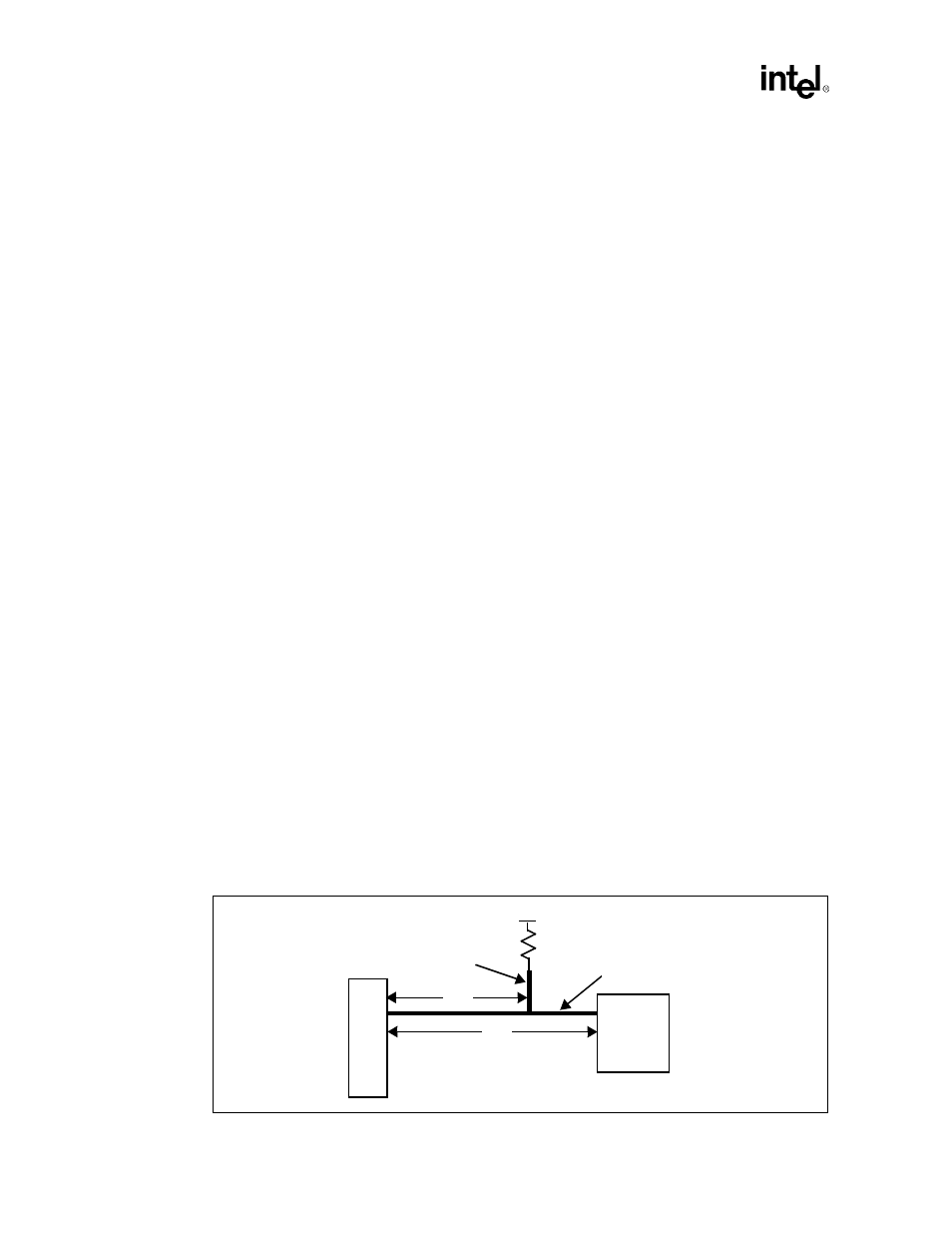
2.3.3
Single Processor Design
2.3.3.1
Single Processor Network Topology and Conditions
The recommended topology for single processor systems is shown in
Figure 2-7
. In addition to the
termination resistor on the Pentium II processor substrate, a termination resistor is placed on the
system board. The recommended value for the termination resistor is 56
Ω
± 5%.
Figure 2-7. Recommended Topology for Single Processor Design
Sl
ot 1
Intel
®
440GX
AGPset
L1
L2
L4
L3
R
TT
V
TT