Intel 440GX User Manual
Page 103
Intel
®
440GX AGPset Design Guide
4-3
Debug Recommendations
The extra loading of the LAI562 requires stronger pull-up values on the target system. However,
due to the current limitations of some signal drivers, this stronger value may not be feasible.
Calculation of the correct pull-up resistor value for each of the CMOS signals should include a load
analysis based on the pull-up voltage, pull-up voltage tolerance, pull-up resistor tolerance, V
IH
and
V
IL
specifications, driver current rating, input current leakage, input timings, etc. The resulting
values may conflict.
As a result of the extra loading the following compromise pull-ups to Vcc
2.5
are recommended.
The actual value required by your system may vary depending on the logic connected and the drive
strength of the signal to the Slot 1 connector.
Inputs to the Slot 1 connector from the ITP562 Port:
•
PREQ#
150 - 330 ohm
•
TDI
150 - 330 ohm
•
TMS, TCK
1 Kohm
•
TRST#
470 - 680 ohm (A pull-down is recommended but a pull-up may
be used)
Inputs to the Slot 1 connector from the PIIX4E:
•
STPCLK#
430 ohm
•
SMI#
430 ohm
•
SLP#
150 - 330 ohm
Outputs from the Slot 1 connector:
•
TDO
150 ohm
•
THERMTRIP#
150 - 220 ohm
•
FERR#
150 - 220 ohm
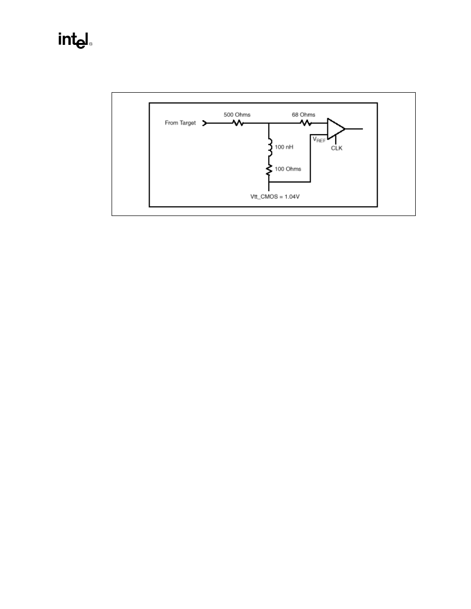
Figure 4-1. LAI Probe Input Circuit