5 agp clock layout – Intel 440GX User Manual
Page 58
Motherboard Layout and Routing Guidelines
2-34
Intel
®
440GX AGPset Design Guide
2.9.6.5
AGP Clock Layout
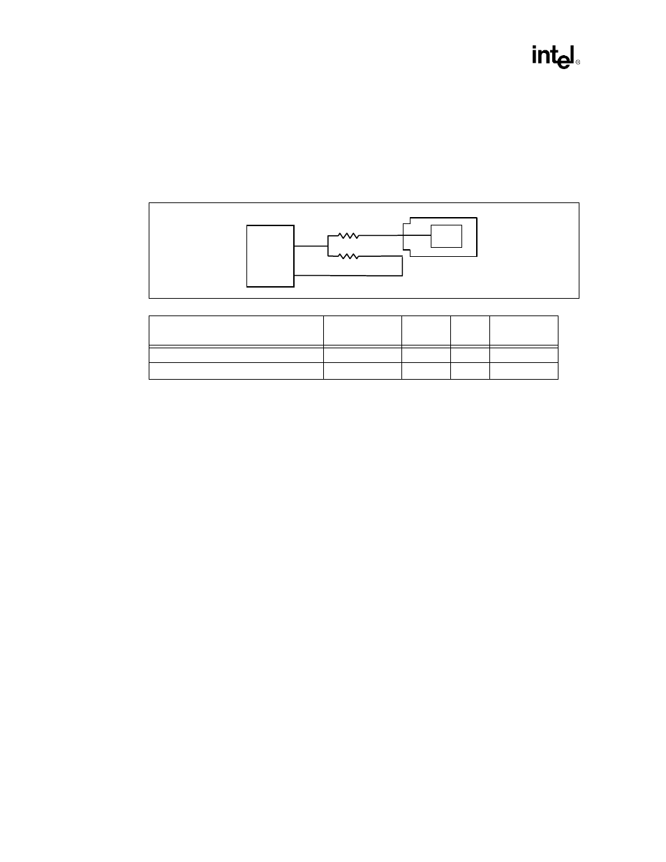
Series Termination: 22 Ohm series termination should be used for the AGP clocks.
Layout guidelines: The feedback clock trace length equals the standard clock motherboard trace
length plus the card trace length.
Note:
One driver. The signal splits at the 82443GX, each half of the trace goes through a 22 Ohm resistor,
and then to their respective loads. If the graphics chip is down on the motherboard, the trace length
to the graphics chip and the feedback trace length to the 82443GX will both be the same length.
Figure 2-31. AGP Clock Layout
Net
Trace Length
Min
Max
Card Trace
Length
22 Ohm resistor - AGP connector
A
0.5”
12”
~3.3”
22 Ohm resistor - 82443GX (feedback)
A + 3.3”
0.5”
15.3”
NA
GCLKOUT
GCLKIN
AGPCLK
BX
22ohm
22ohm
- 41210 (64 pages)
- 8xC251TQ (20 pages)
- ENTERPRISE PRINTING SYSTEM (EPS) 4127 (84 pages)
- U3-1L (20 pages)
- 80960HA (104 pages)
- X58 (54 pages)
- ESM-2850 2047285001R (91 pages)
- ATOM US15W (54 pages)
- D915GVWB (4 pages)
- XP-P5CM-GL (28 pages)
- AX965Q (81 pages)
- CORETM 2 DUO MOBILE 320028-001 (42 pages)
- CV700A (63 pages)
- 80C188EA (50 pages)
- X25-M (28 pages)
- XP-P5IM800GV (26 pages)
- IB868 (60 pages)
- D865GVHZ (88 pages)
- IB865 (64 pages)
- Altera P0424-ND (1 page)
- 8086-2 (30 pages)
- IXDP465 (22 pages)
- IWILL P4D (104 pages)
- GA-8I955X PRO (88 pages)
- FSB400 (PC2100) (96 pages)
- D845GLAD (4 pages)
- NAR-3041 (1 page)
- 87C196CA (136 pages)
- G52-M6734XD (74 pages)
- A96134-002 (10 pages)
- Express Routers 9000 (8 pages)
- 82540EP (45 pages)
- D865GLC (94 pages)
- IB850 (69 pages)
- MB898RF (62 pages)
- Arima LH500 (78 pages)
- V09 (33 pages)
- I/O Processor (22 pages)
- M600 (110 pages)
- SE7520JR2 (63 pages)
- SERVER BOARD S5520HCT (30 pages)
- Extensible Firmware Interface (1084 pages)
- GA-8IPXDR-E (70 pages)
- D845EBG2 (4 pages)
- AW8D (80 pages)