8 agp layout and routing guidelines, 1 agp connector (“up option) layout guidelines – Intel 440GX User Manual
Page 43
Intel
®
440GX AGPset Design Guide
2-19
Motherboard Layout and Routing Guidelines
2.8
AGP Layout and Routing Guidelines
For the definition of AGP Interface functionality (protocols, rules and signaling mechanisms, as
well as the platform level aspects of AGP functionality), refer to the latest AGP Interface
Specification rev 1.0 and the AGP Platform Design Guide. These documents focus only on specific
Intel
®
440GX AGPset platform recommendations for the AGP interface.
In this document the term “data” refers to AD[31:0], C/BE[3:0]# and SAB[7:0]. The term “strobe”
refers to AD_STB[1:0] and SB_STB. When the term data is used, it is referring to one of three
groups of data as seen in
Table 2-12
. When the term strobe is used it is referring to one of the three
strobes as it relates to the data in its associated group.
2.8.1
AGP Connector (“Up Option) Layout Guidelines
The maximum line length is dependent on the routing rules used on the motherboard. These routing
rules were created to give freedom for designs by making trade-offs between signal coupling
(trace spacing) and line lengths. These routing rules are divided by trace spacing. In 1:1 spacing,
the distance between the traces (air gap) is the same as the -width of the trace. In 1:2 spacing, the
distance between the traces is twice the width of the trace.
For trace lengths that are between 1.0 inch and 4.5 inches, a 1:1 trace spacing is recommended for
data lines. The strobe requires a 1:2 trace spacing. This is for designs that require less than 4.5
inches between the AGP connector and the AGP target.
Longer lines have more crosstalk. Therefore, to maintain skew, longer line lengths require a greater
amount of spacing between traces. For line lengths greater than 4.5” and less than 9.5”, 1:2 routing
is recommended for all data lines as well as the strobes. For all designs, the line length mismatch
must be less than 0.5” and the strobe must be the longest signal of the group.
Table 2-12. Data and Associated Strobe
Data
Associated Strobe
AD[15:0] and C/BE[1:0]#
AD_STB0
AD[31:16] and C/BE[3:2]#
AD_STB1
SBA[7:0]
SB_STB
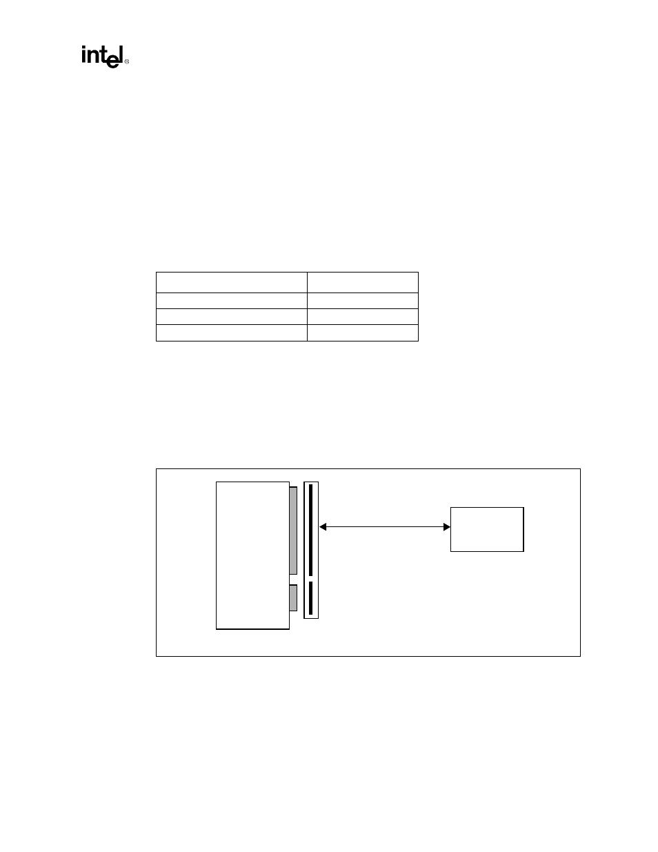
Figure 2-14. AGP Connector Layout Guidelines
AGP
Compliant
Graphics
Device
82443GX
Always 1:2 Strobe Routing
AGP Signal Bundle
1.0” - 4.5”
1:1 (Data) Routing
4.5” - 9.5”
1:2 (Data) Routing
AGP
Connector