Intel 440GX User Manual
Page 81
Intel
®
440GX AGPset Design Guide
3-21
Design Checklist
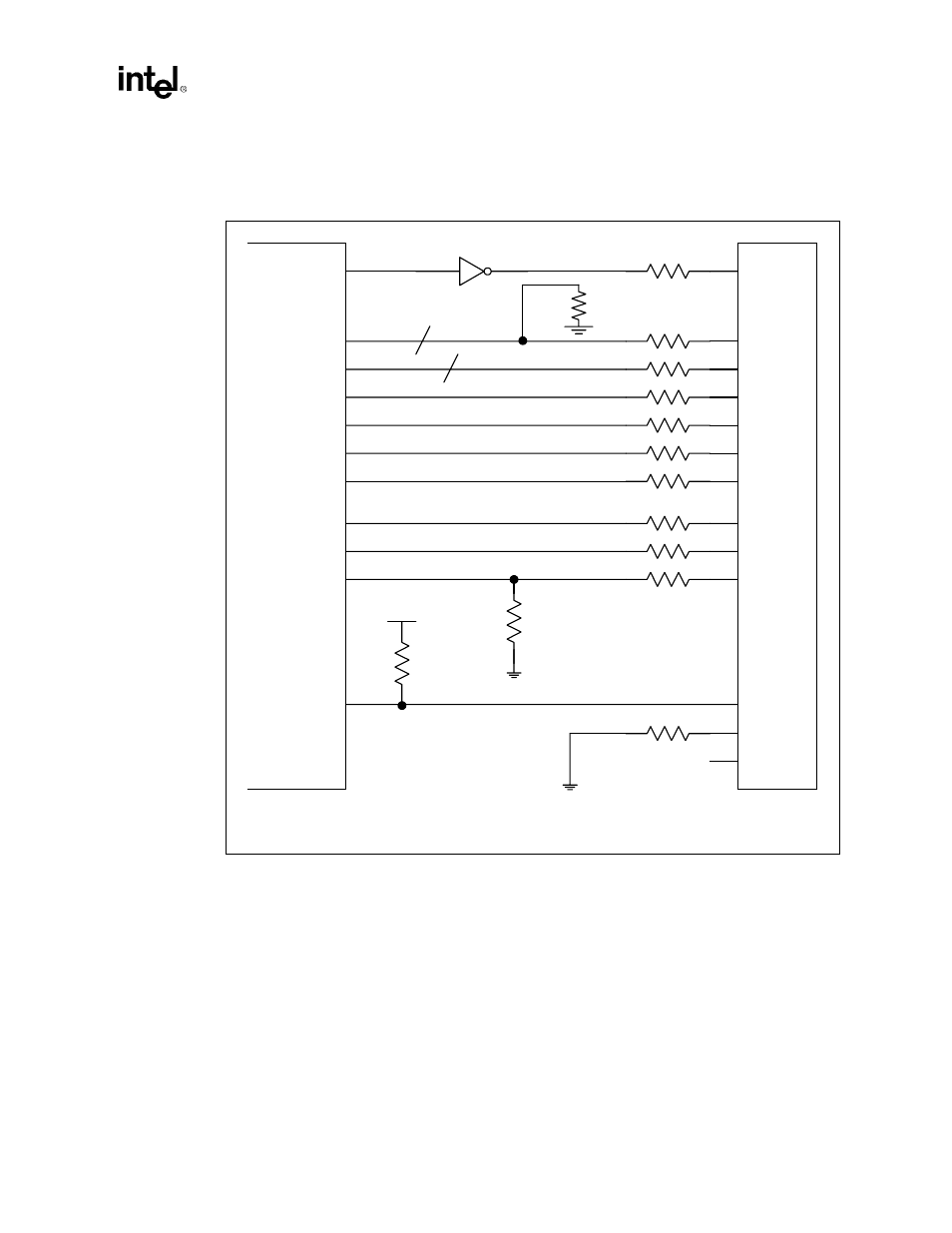
One resistor per IDE connector is recommended for all signals. For signals labeled as 22-47
Ω
, the
correct value should be determined for each unique motherboard design, based on signal quality.
RESET comes from the PIIX4E RSTDRV signal through a Schmitt trigger
The design consideration shown above illustrates the series resistor placement for trace lengths not
exceeding 4 inches. Note that if the trace length between the PIIX4E and the IDE header exceeds 4
inches, the series resistors should be placed within 1 inch of the PIIX4E. The series termination
resistors are required in either design.
Figure 3-4. Series Resistor Placement for Primary IDE Connectors
PDD[15:0]
P D D R E Q
P D I O R #
P D I O W #
P I O R D Y
I R Q 1 4
P D D A C K #
PDA[2:0]
P D C S 1 #
P D C S 3 #
3 3 o h m
3 3 o h m
3 3 o h m
3 3 o h m
1 k o h m
3 3 o h m
3 3 o h m
2 2 - 4 7 o h m
2 2 - 4 7 o h m
4 7 0 o h m
5 . 6 k o h m
5 V
Reset#
Primary IDE Connector
C S E L
Pin32,34
7 4 H C T 1 4
R S T D R V
2 2 - 4 7 o h m
PIIX4E
N . C .
1 0 K o h m
P D D 7
v 0 1 0
3 3 o h m