7 interrupt identity register (iir) – Intel MD566X User Manual
Page 125
56K V.92 Data, Fax, and Voice Chipset
Programmer’s Guide
Intel Confidential
125
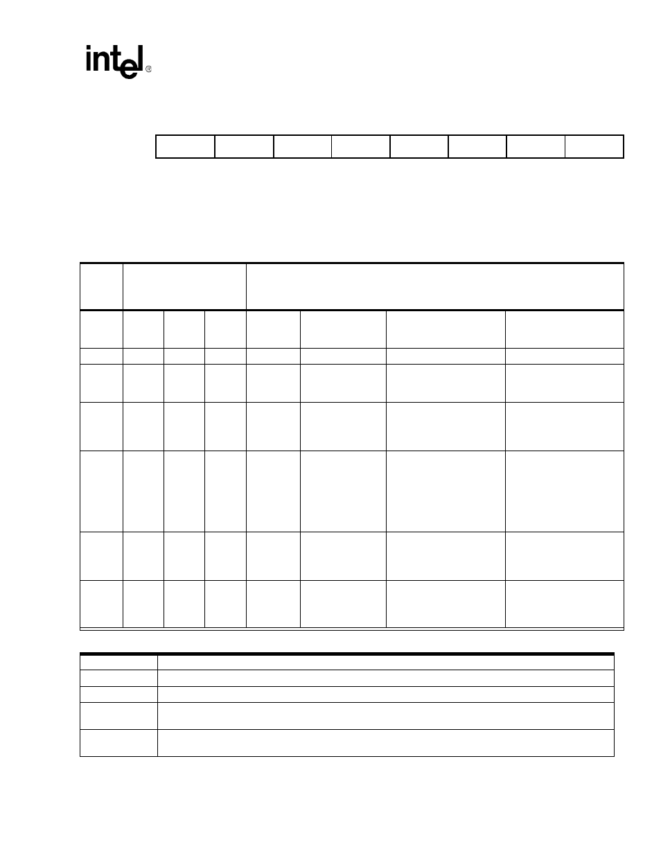
10.1.7 Interrupt Identity Register (IIR)
This read-only register indicates when the transmitter and receiver FIFOs are enabled, and the source of highest-priority pending
interrupt to the DTE. Five levels of modem interrupt sources in order of priority are: receiver line status, received data ready,
character time-out indication, transmitter holding register empty, and modem status. When the DTE reads the IIR, the modem
freezes all interrupts and indicates the highest-priority pending interrupt. While the DTE is reading the IIR register, the modem
records new interrupts but does not change its current indication until the read process is completed.
Table 10-2. Interrupt Control Functions
FIFO
Mode
Only
Interrupt
Identification
Register
Interrupt Source and Reset Functions
Bit 3
ID 2
Bit 2
ID1
Bit 1
ID0
Bit 0
Int.
Pend.
Priority
Level
Interrupt Type
Interrupt Source
Interrupt
Reset Control
0
0
0
1
–
None
None
–
0
1
1
0
Highest
Receiver Line
Status
Overrun Error, Parity
Error, Framing Error or
Break Interrupt
Reading the LSR (Line
Status register)
0
1
0
0
Second
Received Data
Available
Receiver Data Available
or Trigger Level Reached
Reading the RBR
(Receiver Buffer register)
or the FIFO Drops below
the Trigger Level
1
1
0
0
Second
Character
Time-out
Indication
No characters have been
removed from or entered
into the RCVR FIFO dur-
ing the last four character
times, and there is at least
one character in it during
this time
Reading the RBR
(Receiver Buffer register)
0
0
1
0
Third
Transmitter
Holding
Register
Empty
Transmitter Holding
Register Empty
Reading the IIR register (if
the source of interrupt) or
writing into the Transmit-
ter Holding register
0
0
0
0
Fourth
Modem Status
Clear to Send,
Data Set Ready,
Ring Indicator, or Data
Carrier Detect
Reading the MSR
(Modem Status register)
Bits 7:6
FIFOs Enable Bits–These two bits are set whenever FCR0 = 1.
Bits 5
Not used–This bit is permanently set to “0”.
Bit 4
Reserved
Bit 3
Interrupt ID Bit 2–In 16C450 mode, this bit is always a “0”.
In FIFO mode, both this bit and bit IIR2 are set whenever a time-out interrupt is pending.
Bits 2:1
Interrupt ID Bits ID0 and ID1–These two bits are used to identify the highest-priority interrupt as shown
in
.
FIFO EN
FIFO EN
0
VDMA
Int. ID 2
Int. ID 1
Int. ID 0
Int. Pen.
Register 2
(read-only)