GarrettCom 6K16V User Manual
Page 33
Magnum 6K16V Managed Fiber Switch Installation and User Guide (01/04)
26
www GarrettCom com
.
.
color DIP Switch setting ever, and leave it at factory default.
Step 2.
Remove Chassis Cover
The Magnum 6K16V chassis consists of top-bottom, front and rear parts and
assembled together with the help of 18 Philips-head screws. There are 6 screws located
on the front panel of the unit (2 each on top and the bottom and one each at the side), 12
for top-bottom cover of the unit (6 each on the bottom side of the unit) and 6 screws
each on the sides and 6 screws for the rear panel (2 each on top and bott0m and one each
on the side). Remove these screws. Once these screws are removed, the front panel is
easily slid out to the front of the
chassis base.
Figure 3.6.1a: Removing the
Front panel from the unit
Caution: Be careful
not to disturb the
power supply.
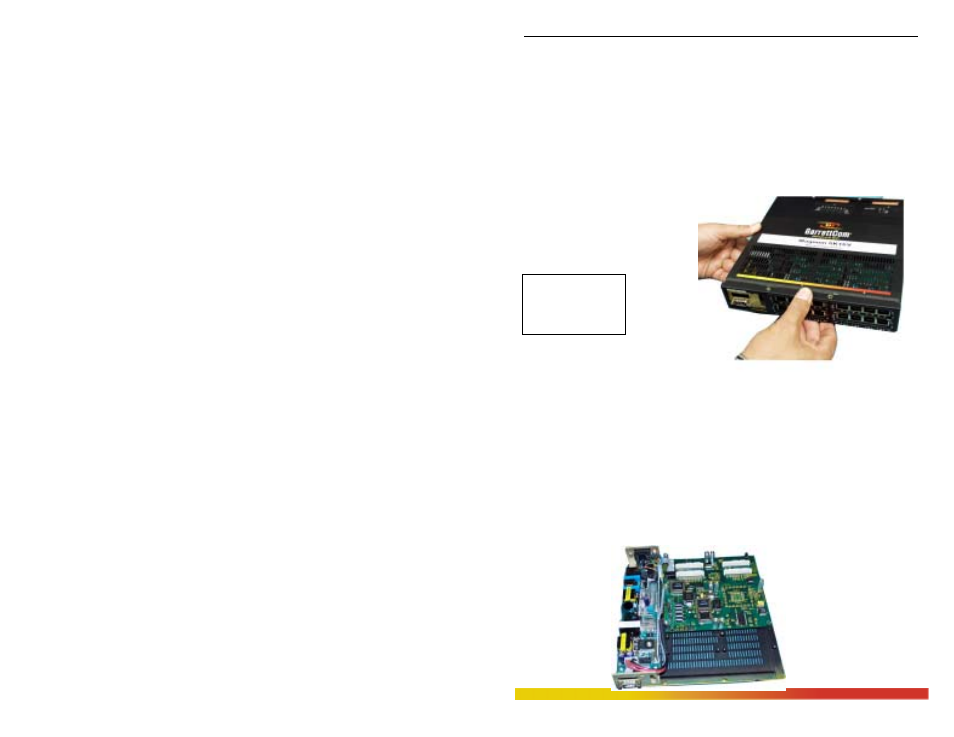
Once the front panel is
removed, the front cover may be slid
out to the front of the unit. Hold on
the back part and then carefully and slowly slide out the top chassis cover towards the
front side, as shown in the picture.
When the chassis top cover has been removed, the interior of the unit is
exposed. Looking down into the Magnum 6K16V unit, notice that there are individual
PM installation spaces and female latch (white) connectors provided on the main board
along with four stand-off’s for each 6KPM card position. (See Figure 3.6.1b).
Figure 3.6.1b: Magnum 6K16V, Top view without chassis cover