GarrettCom 6K16V User Manual
Page 31
Magnum 6K16V Managed Fiber Switch Installation and User Guide (01/04)
24
www GarrettCom com
.
.
to the unit.
Power supply options are available to suit the 6K16V Switches to special high-
availability communications and/or heavy industrial-grade applications, including:
* -48VDC, 24VDC and 125VDC with single DC input,
* -48VDC, 24VDC and 125VDC with dual-source DC input,
See the Appendices of this manual for more details. Use an RFQ for other variations.
3.5 Alarm Contacts for monitoring internal power, and Software Traps
The Alarm Contacts feature, standard on Magnum 6K16V’s, provides two
Form C Normally Closed (NC) contacts to which the user can attach two sets of status
monitoring wires at the green terminal block. The first (top position) NC Alarm Contact
is held open when there is power on the main board inside of the 6K16V. This provides
a “Hardware Alarm” because the NC contacts will close when internal power is lost,
either from an external power down condition or by the failure of the power supply
inside of the Magnum 6K16V Switch.
The second NC Alarm Contact (bottom position) is a “Software Alarm”,
operated by user settings in the MNS-6K software. The user can disable the Software
Alarm feature with a software configuration command if desired. When the Software
Alarm is enabled, the Form C Normally Closed (NC) contact is held open during normal
software operation. A user-defined software malfunction, such as an SNMP Trap or a
Software Security violation or an S-Ring Fault, causes the contact to close and thus
trigger an alarm in the user’s monitoring system. For detail information about the
Software Alarm and software control of SNMP alarm traps, please reference the
Magnum MNS-6K Software User Manual.
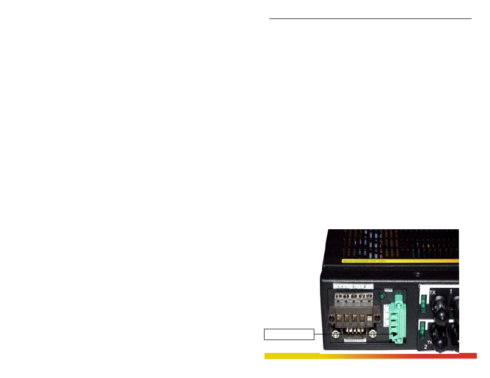
The Alarm Contacts are on the front left area (next to the DC power source)
of the Magnum 6K16V unit and is green in color as shown in the picture below.
Relay Contacts